
Custom Electronic Devices PCBA, Component Procurement and DIP Assembly: Let Run Hours Set the Maintenance Date
A standard maintenance calendar operates on a flawed assumption: that every production line accumulates mechanical wear at an identical, predictable pace. In reality, a solder stencil endures vastly different stress during a forty-thousand-panel rush week than during a quiet prototyping week, and a moisture-sensitive component reel stored during humid summer months degrades far faster than one stored in dry winter conditions. Drawing from years of operating High Precision SMT Assembly Lines Factory floors alongside through-hole benches and component warehouses, one operational rule consistently outperforms calendar schedules: let each piece of equipment report its actual cumulative wear, and trigger maintenance directly from machine telemetry.
Surface-mount placement floors, through-hole wave soldering benches, and component storage warehouses operate under completely different physical conditions, shift patterns, and thermal environments. Yet all three share strict delivery deadlines where unexpected downtime creates costly bottlenecks. Rather than asking whether equipment appears functional on a scheduled date, production leads must identify which asset will fail first based on the operational metrics it is already generating.
Why Calendar Maintenance Fails on High-Mix Production Floors
Traditional preventive maintenance checklists rely on arbitrary intervals—such as wiping stencils every Friday or inspecting solder pots on the first of the month. A calendar cannot distinguish between three short engineering runs and continuous high-volume production. On an active electronics manufacturing floor, the meaningful unit of wear is cumulative operational cycles: squeegee strokes per stencil, feeder index advances per component reel, thermal hours per reflow oven zone, and board passes per solder wave. Modern machine controllers already log these exact metrics; production teams simply need to convert those readouts into mandatory maintenance triggers.
Shifting from calendar dates to run-hour triggers eliminates debate during shift handovers. During low-volume weeks, maintenance teams avoid unnecessary teardowns that introduce setup variation. During peak production surges, equipment receives immediate service the moment cycle thresholds are crossed—preventing mid-lot defects before they reach inspection stations.

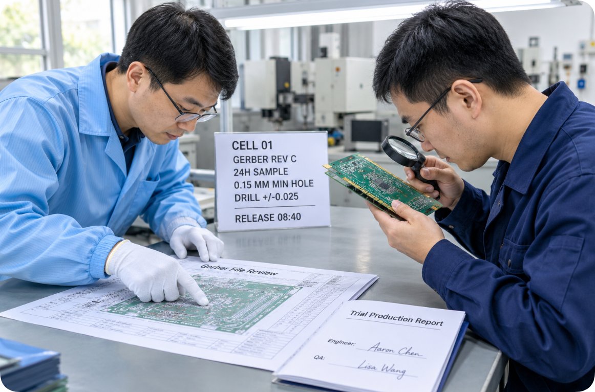
Monitoring real-time machine run hours and cycle counts on high-precision PCBA assembly lines
SMT Placement Floor: Tracking Stencil Print Counts and Reflow Oven Hours
Surface-mount lines provide the richest real-time diagnostic data because every stage—from solder paste printing and 3D Solder Paste Inspection (SPI) to multi-zone reflow soldering, Automated Optical Inspection (AOI), and X-ray verification—logs panel-by-panel telemetry. Inside a Consumer Electronics PCBA Assembly Factory running high-mix assemblies, lines frequently transition between ultra-fine-pitch components and larger connectors within a single shift. Calendar-based maintenance breaks down under high-mix changeovers because cumulative mechanical wear continues unabated regardless of product SKU changes.
Three core metrics provide the earliest warning of impending SMT process drift:
- Cumulative Stencil Print Count: Every squeegee stroke gradually wears stainless-steel aperture walls and builds paste residue. When placing 0201 passive components or fine-pitch BGAs, worn apertures cause insufficient solder volume and bridging long before a scheduled weekly wash.
- Reflow Oven Zone Operating Hours: Heating elements, blowers, and flux management traps degrade gradually over hundreds of thermal hours. Minor temperature profile drift triggers solder voiding and tombstoning well before an oven controller reports an alarm.
- SPI and AOI Callout Trends (DPMO): Tracking defect callouts per thousand placements reveals subtle feeder pitch wear or nozzle vacuum degradation while yields are still within tolerance.
Supporting equipment—including ultrasonic stencil cleaners and component baking ovens—follows the same discipline. Bare PCBs and moisture-sensitive devices exposed during humid periods require verified baking durations tracked by cumulative exposure hours rather than arbitrary weekday schedules.
Component Sourcing & Warehousing: Managing Moisture Exposure Clocks
Warehouse and procurement teams often overlook run-hour discipline because passive reels on storage racks have no moving motors. However, electronic components age dynamically once removed from factory vacuum-sealed moisture barrier bags. Moisture Sensitivity Level (MSL) floor life begins ticking the exact minute a dry pack is unsealed—not on the supplier invoice date. A reel left unsealed in a humid staging zone for forty-eight hours has already consumed a substantial portion of its safe assembly window, risking popcorn cracking during reflow soldering. That is why rigorous BOM Electronic Component Sourcing & Procurement tracks environmental exposure as an active lot parameter rather than a static receiving checkbox.
Effective warehouse telemetry combines incoming Acceptable Quality Limit (AQL) sampling results, up-to-date supplier audit records, and continuous temperature-humidity logging across dry cabinets. When an individual lot exceeds its cumulative out-of-bag exposure threshold, automated condition logs flag that specific reel for mandatory baking or quarantine before it ever reaches an SMT feeder—preventing latent solder joint failures across entire production batches.

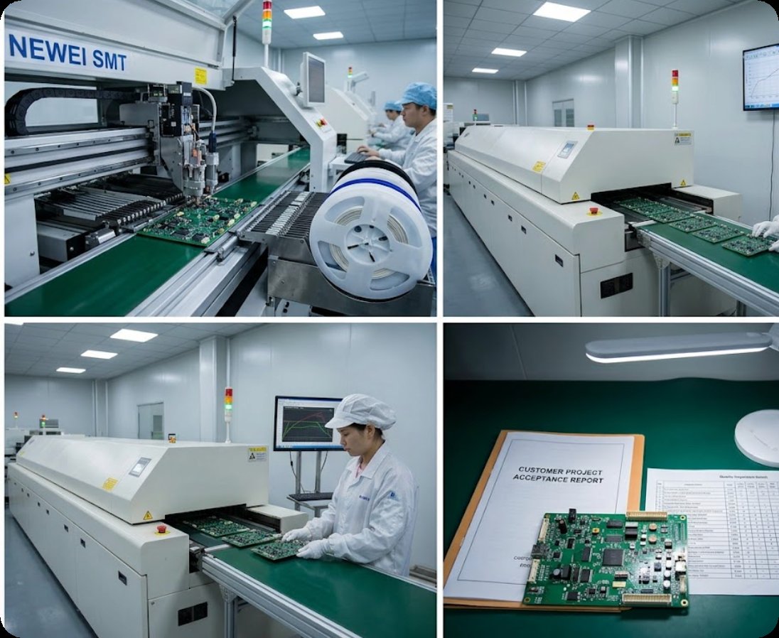
Tracking moisture-sensitive floor life and environmental exposure hours in component storage warehouses
Through-Hole Assembly: Monitoring Wave Solder Chemistry and Fixture Cycles
Through-hole production lines accumulate mechanical and metallurgical wear differently from automated surface-mount equipment. Solder pot alloy composition gradually shifts due to copper dissolution and dross formation over operating hours, wave nozzles accumulate flux residue as boards pass across the crest, and manual or semi-automated insertion fixtures loosen incrementally under repetitive clamping forces. In facilities running DIP Through Hole Assembly & Wave Soldering alongside SMT lines, legacy industrial assemblies frequently run on steady schedules—making it tempting to defer bench maintenance until visible solder defects appear.
Three practical meters keep through-hole operations predictable: insertion cycles per mechanical fixture, operating hours since the last solder pot metallurgical analysis, and defect categorization at post-wave QC inspection stations. Furthermore, wave soldering wear depends heavily on board density; running heavy multi-pin power connectors depletes flux and stresses solder waves faster than sparse control boards. Weighting wave operating hours by total solder joint count converts subjective operator impressions into exact service triggers.

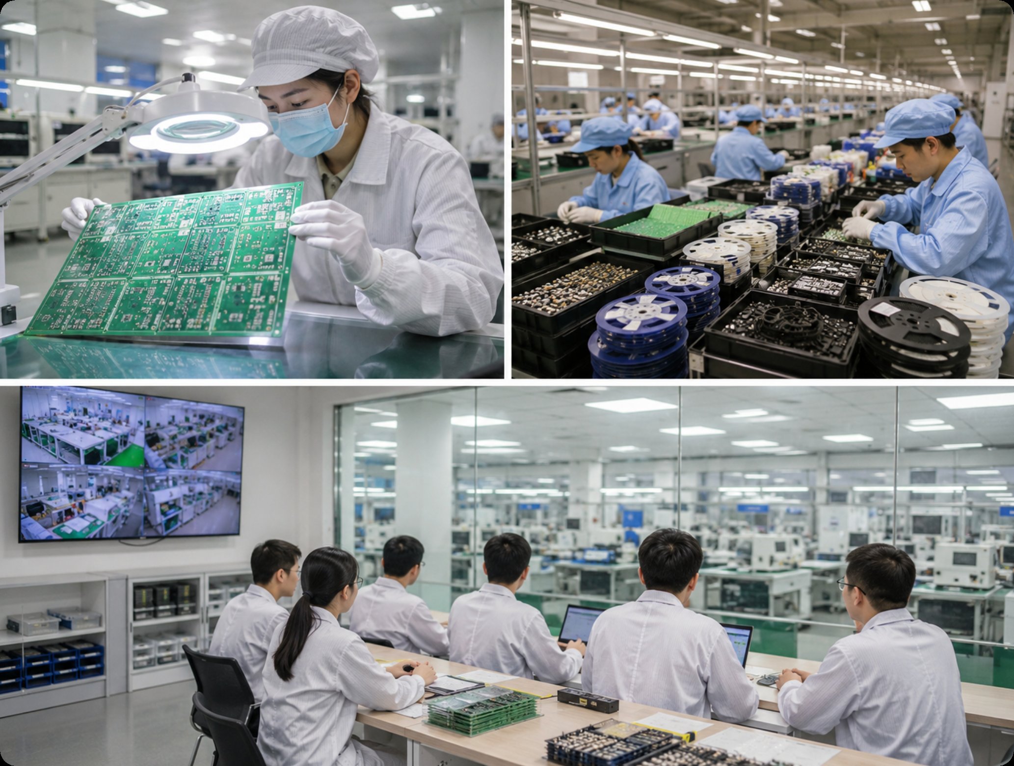
Logging wave soldering run hours and insertion fixture cycles on DIP through-hole production lines
Unified Run-Hour Maintenance Matrix Across SMT, Sourcing, and DIP
Consolidating SMT assembly, component warehousing, and DIP through-hole operations onto a single daily maintenance log gives production managers full visibility without distorting distinct physical metrics into artificial percentages:
| Manufacturing Service | Primary Wear Meter | Early Process Drift Signal | Actionable Maintenance Trigger |
|---|---|---|---|
| Custom Electronic Devices PCBA (SMT) | Prints per stencil; cumulative reflow zone hours | Rising SPI/AOI callouts per 1,000 placements | Clean stencil at print threshold; re-profile oven at zone-hour limit |
| Component Procurement & Storage | Out-of-bag exposure hours after unsealing | Humidity/temperature condition log alert on specific lot | Bake or quarantine reel at MSL exposure limit, not monthly dates |
| DIP Through-Hole Assembly | Insertions per fixture; joint-weighted wave hours | Localized solder defect spike on specific fixture | Calibrate fixture at cycle limit; test solder alloy at joint-hour limit |
Operational Boundaries: What Run-Hour Telemetry Cannot Replace
Telemetry-driven maintenance relies entirely on disciplined data capture at the point of use. If operators estimate cycle counts at the end of a shift rather than pulling direct readouts from machine controllers and dry-cabinet sensors, a run-hour sheet quickly degrades into guesswork. Any estimated figure must be explicitly flagged so engineers never mistake approximations for verified sensor telemetry.
Additionally, run-hour logs detect mechanical wear and environmental drift—they cannot compensate for underlying Design for Manufacturability (DFM) flaws. If a PCB layout positions thermal-sensitive fine-pitch components directly adjacent to high-mass heat sinks, or uses non-standard pad geometries, solder defects will persist even on freshly calibrated lines. Integrating telemetry across Turnkey EMS Electronic Manufacturing Services allows engineering teams to separate true equipment wear from PCB layout issues early in production.
Empowering Line Ownership and Rapid Shift-Handover Protocols
A maintenance threshold only protects product quality when frontline operators have direct authority to halt production the moment a limit is reached. On well-run floors, the SMT line lead owns stencil print counts, warehouse technicians own reel exposure logs, and through-hole operators own fixture cycle counts. Requiring management committee approval to pause a machine for threshold maintenance guarantees that limits will be ignored during rush orders. Just as Quick Turn PCB Prototyping & Board Manufacturing teams enforce strict first-article verification after every restart, production lines must log every threshold stop and verify first-piece quality before resuming full speed.
Sustaining this discipline takes less than two minutes during the first ten minutes of every shift handover by reviewing three questions: which meters crossed a limit, which assets are approaching a threshold during the upcoming shift, and which entries were estimated rather than machine-logged. For a practical example of how historical station logs trace root causes after field testing, review our engineering case study on Shell Mold and Aging Test protocols.
Frequently Asked Questions (FAQ)
1. Yes, scheduling electronics manufacturing maintenance by machine run hours and cycle counts is significantly more reliable than relying on fixed calendar dates.
Solder stencils, reflow oven zones, and wave solder pots accumulate physical wear proportionally to production volume rather than elapsed days. Tracking actual cycles prevents premature maintenance during slow periods and eliminates mid-run equipment drift during high-volume rushes, reserving calendar dates strictly for shelf-life expiration on sealed materials.
2. Yes, stencil print counts and SPI/AOI defect callout rates per thousand placements are the two highest-impact metrics to track first on an SMT line.
Modern printers and inspection machines already record these figures automatically. Monitoring both metrics together detects stencil aperture wear and subtle placement alignment drift early, allowing technicians to clean or recalibrate equipment before defective PCBA lots are produced.
3. Yes, component procurement and warehousing integrate directly into run-hour maintenance by tracking out-of-bag moisture exposure hours.
Logging the exact timestamp when a moisture-sensitive reel is unsealed alongside ambient storage humidity and AQL inspection results enables warehouse teams to bake or quarantine specific exposed lots before they cause reflow solder defects on the assembly floor.
4. Yes, a single unified maintenance log can effectively manage SMT assembly, component storage, and DIP through-hole operations simultaneously.
Keeping each department's native wear unit separate—stencil prints for SMT, exposure hours for component reels, and joint-weighted wave hours for DIP—provides program managers with clear, comparable visibility across the entire turnkey manufacturing workflow without distorting technical data.
The video below demonstrates SMT assembly line quality control, SPI/AOI inspection workflows, and preventive equipment maintenance in electronics manufacturing.
Tags: SMT assembly / PCBA / DIP assembly / component procurement / maintenance tips /
Prev: Custom Smart Home Products PCB and Shell Mold: The Delivery Unit Behind Each Comparison Row
Next: No more...