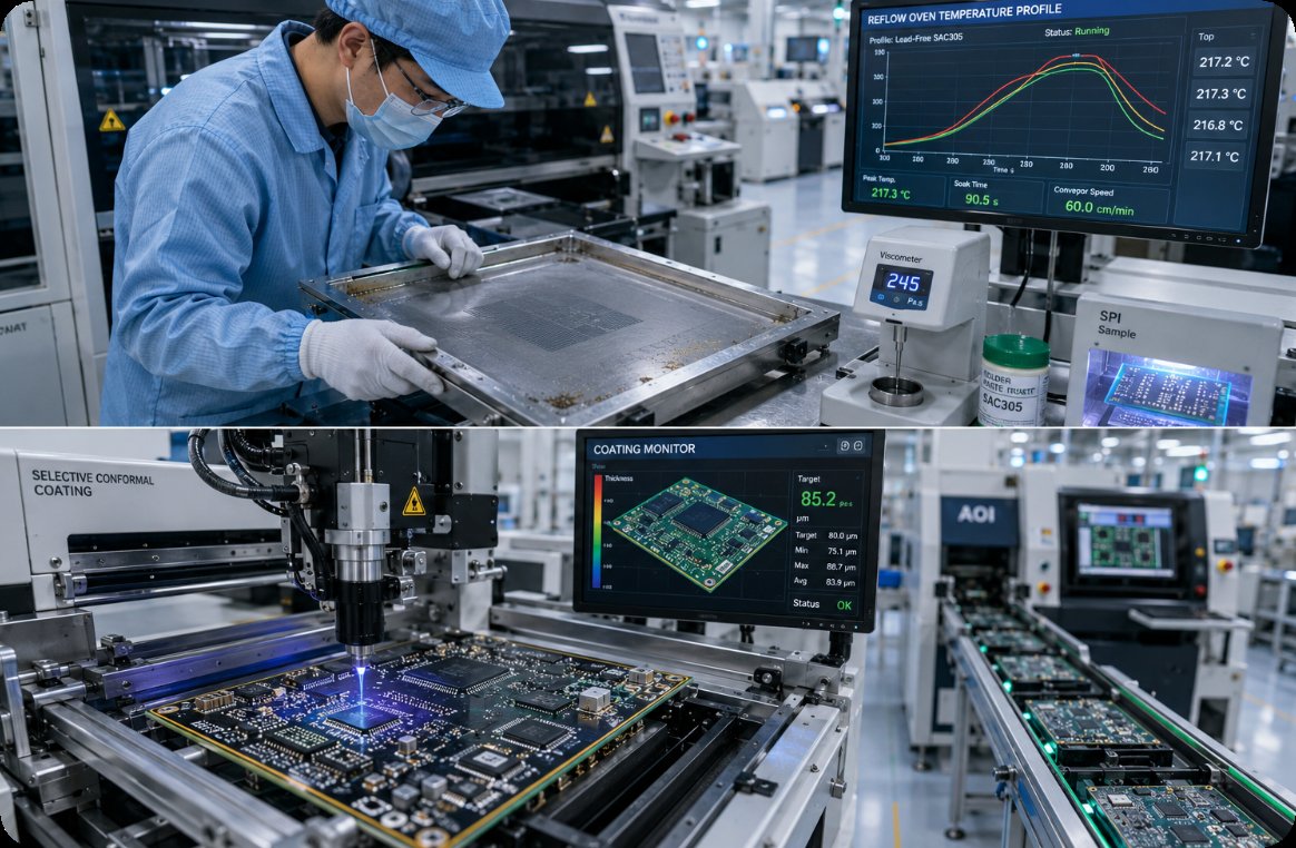

Custom Smart Home Products PCB and Shell Mold: The Delivery Unit Behind Each Comparison Row
When procurement engineers line up three electronics manufacturing suppliers in a spreadsheet, they typically copy the exact same column headings across every row: lead time, technical capability, certification, and unit quantity. The analytical breakdown occurs one line lower, where every supplier writes the identical acronym—PCB. On a bare-board fabrication specification sheet, that term designates an unpopulated laminate panel awaiting components. On a surface-mount assembly schedule, it designates a fully populated circuit board backed by a complex bill of materials (BOM). On an injection molding quote, it frequently conflates one-time steel tooling with recurring plastic enclosure batches. All three rows appear comparable on paper, yet none measures the same physical deliverable. This technical audit defines what each procurement row actually measures—relying strictly on published NEWEI engineering parameters while explicitly marking unpublished metrics rather than guessing.
Distinguishing these counting rules is critical for hardware programs combining a consumer control board, an industrial motherboard, and a custom enclosure. Those three deliverables operate on completely different production clocks, arrive in distinct packaging formats, and follow separate accounting units. Merging them into a single undifferentiated comparison table conceals severe schedule and cost discrepancies until the first supplier invoice arrives or an assembly line stalls due to a missing sub-assembly. Specifying the exact delivery unit beside every line item prevents these procurement errors before quotations are even opened.
Why a Fabrication Panel Stops at the Edge of the Bare Board
A bare-board fabrication specification defines raw substrate geometry rather than a functional electronic assembly. Published NEWEI fabrication capabilities extend up to 40 conductive layers, plate thicknesses ranging from 0.4 mm to 8.0 mm, maximum working panel dimensions of 2000 × 610 mm, and minimum trace width and spacing tolerances of 0.065 × 0.065 mm. Additional verified metrics include drilling positional accuracy within ±0.025 mm, minimum mechanical hole diameters of 0.15 mm (with 0.35 mm pads), and specialized processes including High-Density Interconnect (HDI), blind and buried vias, BGA pads, hard gold fingers, resin-plugged vias, and laser micro-drilling. None of these parameters accounts for active silicon, passive components, connectors, or housings—they strictly govern copper etching, mechanical drilling, and dielectric lamination.
Furthermore, bare-board prototyping advertises 24-hour rapid circuit board sampling based on submitted Gerber archives and an engineering inquiry form, concluding with a formal trial production report documenting design-for-manufacturability (DFM) findings. The physical unit counted here is an unpopulated board blank departing the fabrication press. Procurement teams evaluating vendors via the Quick Turn PCB Prototyping & Board Manufacturing capability matrix are strictly benchmarking bare-substrate manufacturing speed. Projecting that 24-hour bare-board turnaround onto populated assembly rows is the primary cause of schedule miscalculation.
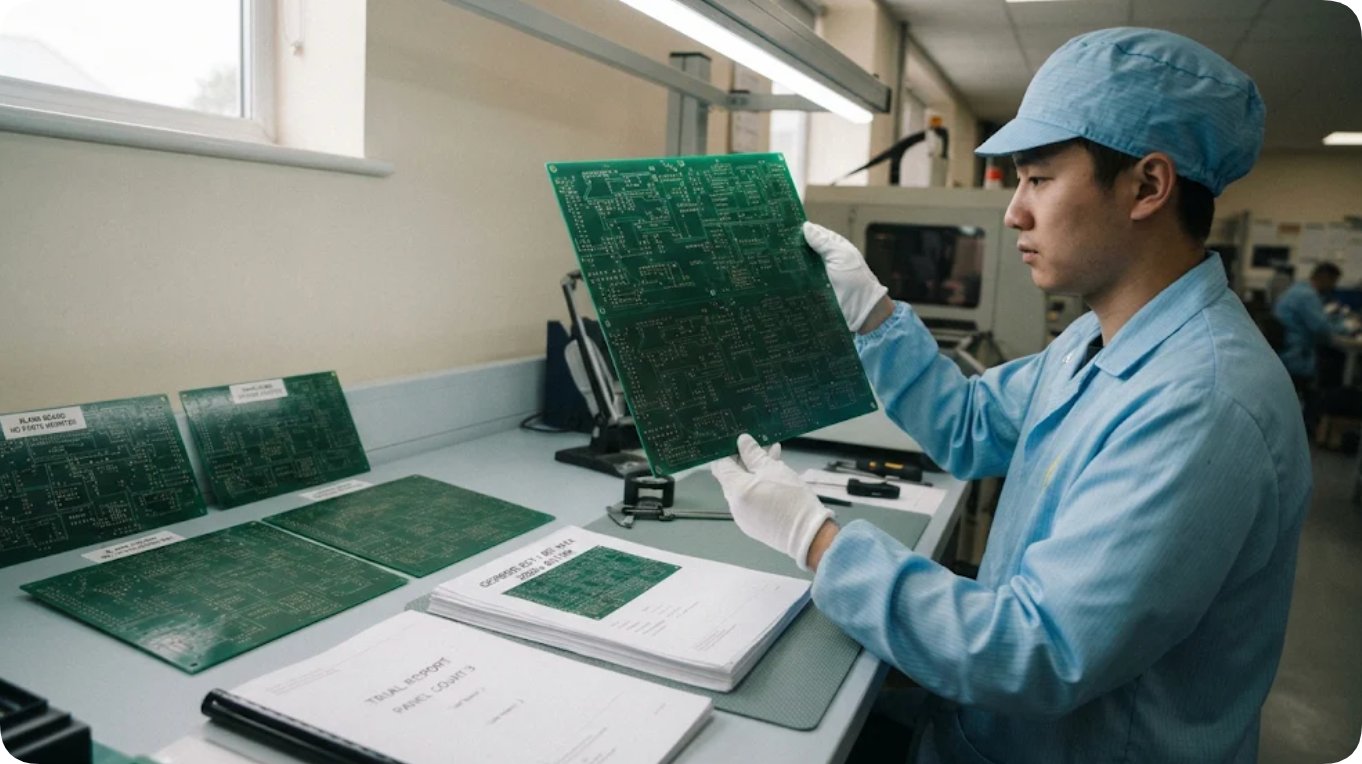
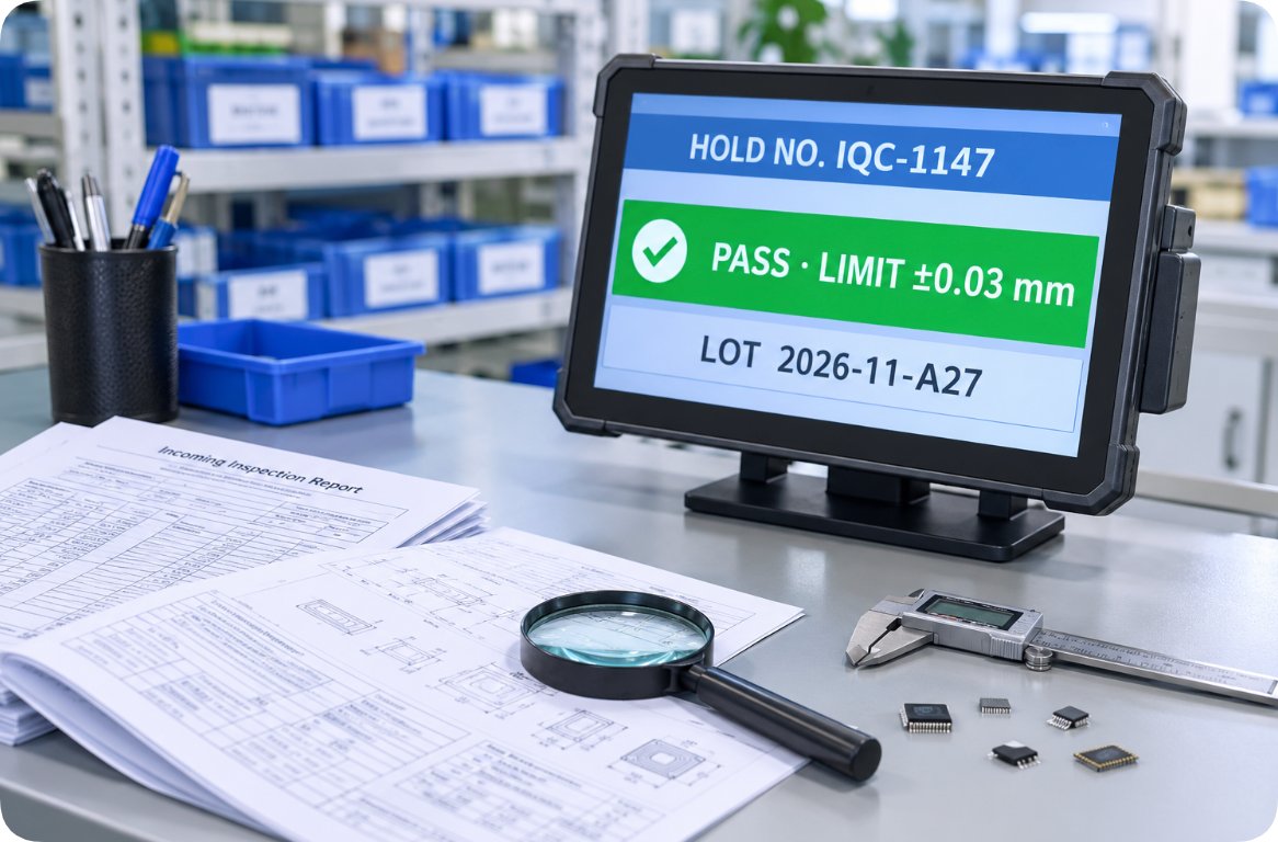
Bare PCB fabrication counts unpopulated copper-etched laminate panels defined strictly by Gerber data
Populated PCBA Assemblies Carry Components and Verification Scope
A populated printed circuit board assembly (PCBA) represents a completely distinct procurement transaction. Before releasing an assembly quotation, Surface Mount Technology (SMT) engineering requires a complete Bill of Materials (BOM), verified Gerber files, and centroid pick-and-place coordinate files. Manual through-hole soldering and custom wave-soldering pallets are priced as separate non-recurring engineering (NRE) mechanisms rather than hidden inside per-unit board rates. Once component kits and bare boards are verified in stock, standard SMT production lead times initiate at 3 to 5 working days (excluding statutory public holidays), supported by four automated high-speed placement lines capable of handling 0201 passive components, 0.4 mm fine-pitch BGAs, and QFN packages under Solder Paste Inspection (SPI), Automated Optical Inspection (AOI), and 3D X-ray verification.
Similarly, showcase catalogs such as the Smart Home Electronics PCBA OEM ODM Supplier overview and the Industrial Computing IPC Motherboard Manufacturer portfolio document turnkey system integration rather than raw laminate specs—intentionally omitting bare-board layer counts or substrate thicknesses. Leaving those cells blank rather than importing figures from a bare-board table maintains analytical discipline: a smart home controller and an industrial IPC motherboard may utilize identical placement lines, yet the delivered unit is a functionally tested electronic assembly.
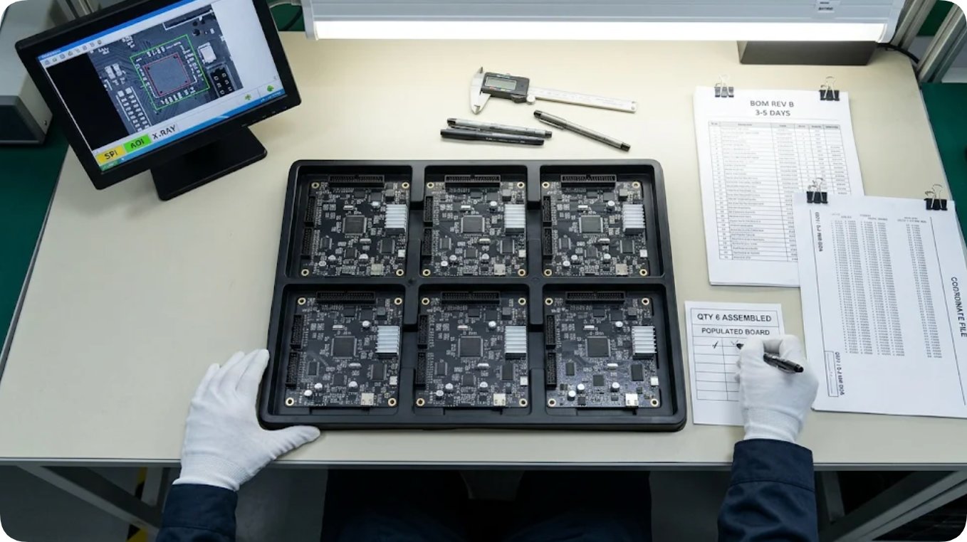
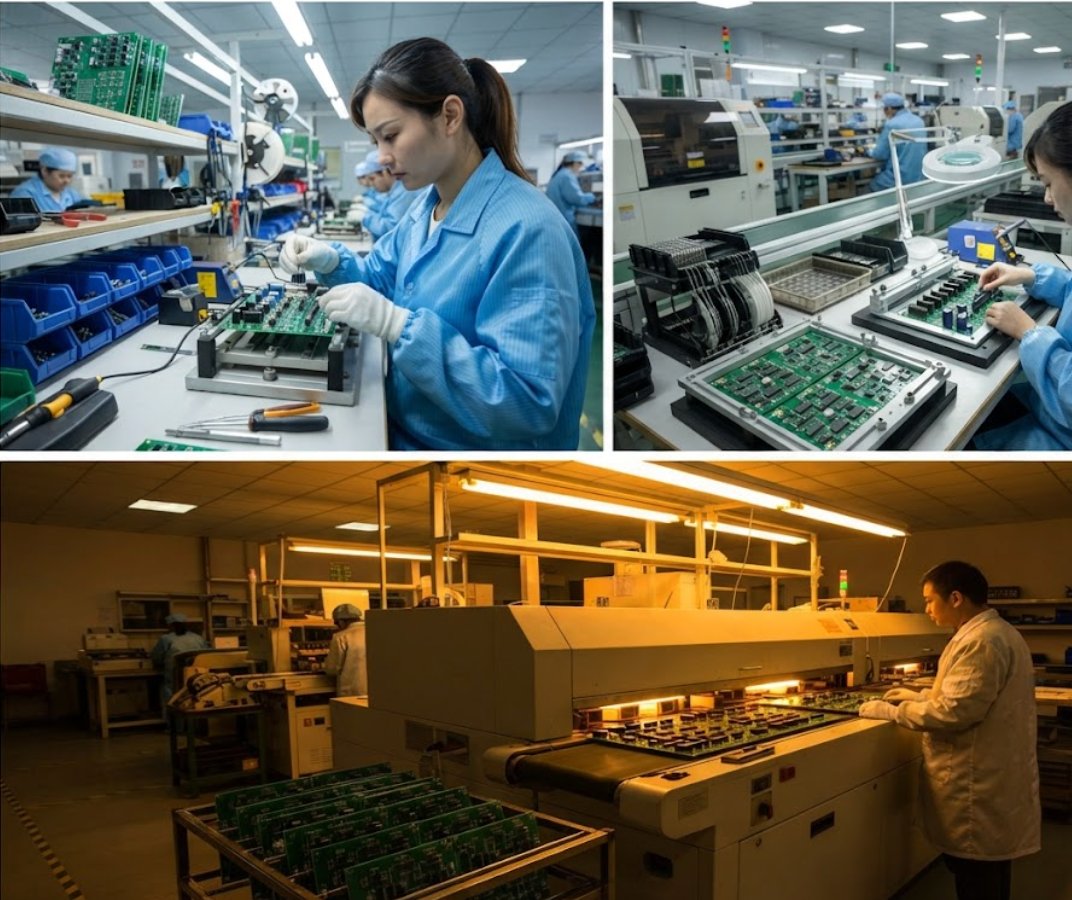
Populated PCBA trays count tested electronic assemblies governed by BOM, coordinate files, and AOI/X-ray verification
Tooling Ships Once, While Production Housings Ship by the Carton
Enclosure manufacturing shifts the unit of measurement once again. Injection molding capabilities specify no minimum order quantity (No MOQ), offering 3D rapid prototyping, small-batch pilot verification runs, and full-scale volume production supported by rapid structural iteration and buffer component inventories. Expanded Electronic Manufacturing Services (EMS) infrastructure incorporates dedicated partner tooling facilities operating over 20 injection molding presses alongside in-house surface finishing—including acoustic/decorative oil spraying, silk-screen printing, pad transfer printing, sub-assembly integration, and precision laser engraving. Here, the commercial deliverable divides cleanly into two separate accounting items: a physical mold tool engineered and validated once, followed by molded plastic housings counted per production carton.
Evaluating the Plastic & Metal Enclosure Injection Mold Manufacturing service as if it were an electronic board row creates immediate spreadsheet distortion. Capital allocated to tooling amortizes engineering design, T1 sample validation, and steel machining; unit pricing allocated to housings reflects resin weight, cycle time, and secondary cosmetic finishing. Hardware programs requiring both custom circuit assemblies and fitted enclosures must maintain separate ledger rows for tooling and unit housings from day one, even when consolidated under a single turnkey manufacturer.
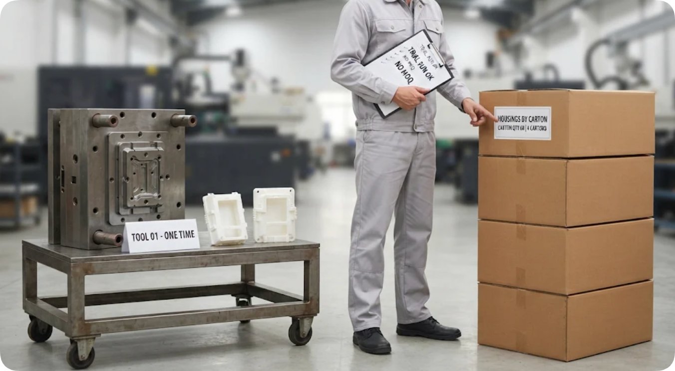
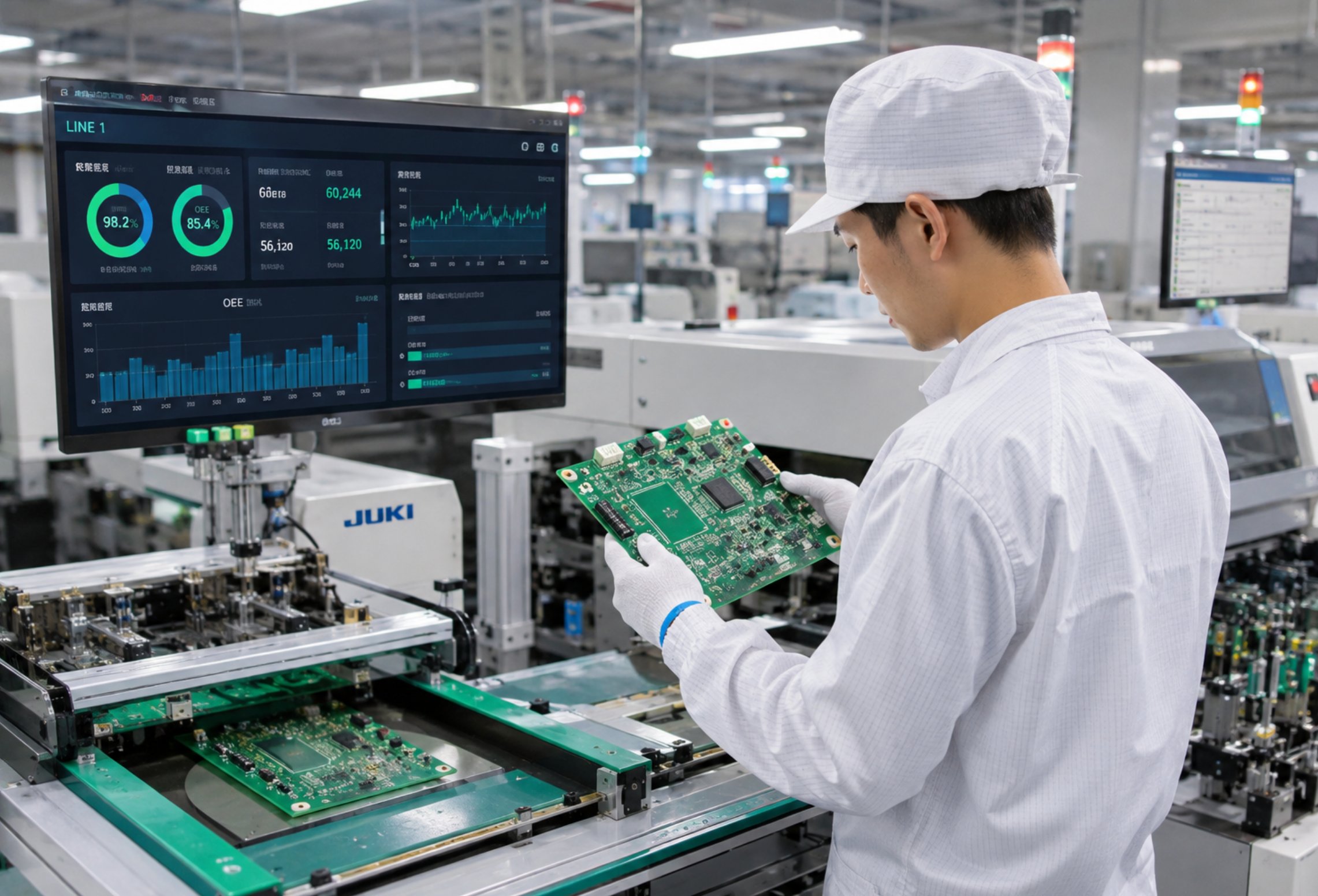
Enclosure procurement separates one-time validated injection molds from recurring production housing batches
Aligning Counting Rules Across Stages on the Procurement Matrix
Three distinct accounting rules emerge from these service specifications. Bare fabrication counts board panels quoted against Gerber files; PCBA assembly counts populated, tested boards quoted against BOMs and coordinate data with separate fixture charges; and enclosure molding counts a validated tool once before counting repeatable housing batches. Placing a 24-hour bare-board sampling promise alongside a 3-to-5-day SMT assembly window and a No-MOQ tooling policy in the same spreadsheet column creates the illusion of competing lead times, when those figures actually represent sequential stages of a single hardware build.
| Procurement Row Label | Counting Unit | Physical Deliverable | Primary Cost & Schedule Drivers |
|---|---|---|---|
| Bare Panel Fabrication | Board blanks / working panels | Unpopulated etched copper laminate | Layer count, panel dimensions, drill tolerance, surface finish |
| Populated PCBA Assembly | Assembled circuit units | Soldered & verified PCBA | BOM line count, component pitch, SPI/AOI/X-ray inspection scope |
| Enclosure Mold Tooling | Validated steel/aluminum mold | One production tool + T1 sample parts | 3D prototyping, cavity complexity, trial verification iterations |
| Production Housing Batch | Molded repeat parts | Cartons of finished enclosures | Batch volume, resin grade, spraying, silk-screening, laser engraving |
Why Initial Pilot Orders and Repeat Production Switch Accounting Units
A first pilot production order and a tenth repeat production run never share identical cost structures, even when hardware designs remain frozen. Initial pilot builds absorb one-time non-recurring engineering (NRE) deliverables: injection mold machining, 3D sample verification, custom wave-soldering pallets, and bespoke Functional Circuit Test (FCT) fixtures tailored to customer test points. Subsequent volume orders strictly purchase recurring unit deliverables. Amortizing initial NRE tooling costs across a small pilot batch artificially inflates per-board unit economics unless separated onto dedicated ledger lines.
Plant-level capacity figures—such as NEWEI's monthly circuit board throughput of 50,000 square meters, four finished-product assembly lines, and adherence to IPC-A-610E Class II workmanship standards—belong in vendor qualification columns rather than per-order quantity cells. Recording exact population definitions alongside every statistical sample keeps quality audits unambiguous.
Audit Documentation That Verifies Each Deliverable Stage
Engineering documentation provides the most reliable audit trail for verifying which physical deliverable was procured. Bare fabrication generates Gerber archives and a DFM trial production report; SMT assembly generates BOMs, centroid files, and SPI/AOI/X-ray inspection logs; enclosure tooling generates 3D sample sign-offs and pilot molding reports.
Final system integration introduces dedicated quality gates. As detailed on the Box Build Product Assembly & Packaging Service specification, finished product assembly enforces workstation self-inspection, 100% QC testing, online QA sampling, and Out-of-Box Audit (OBA) unboxing verification prior to shipment, utilizing segregated material staging zones to prevent component cross-contamination.
| Service Ledger | Published Engineering Metrics | Explicitly Unpublished (Requires RFQ) |
|---|---|---|
| PCB Fabrication & Sampling | Up to 40 layers; 0.4–8.0 mm thickness; 2000 × 610 mm panel; 0.065 mm trace/space; 24-hour rapid sampling | Component counts, assembly yields, finished product mass |
| SMT & PCBA Assembly | 3–5 day window (materials in stock); 4 high-speed lines; 0201, 0.4 mm BGA, QFN; SPI, AOI & X-ray inspection | Fixed unit prices, per-board assembly rates, showcase layer counts |
| Shell Molding & EMS | No MOQ policy; 3D sampling; trial verification; 20+ molding presses; 50,000 m²/month plant capacity | Guaranteed mold shot life, carton packing density, warranty duration |
Marking unpublished parameters explicitly as "Not Published — Confirm at RFQ" prevents procurement teams from accidentally borrowing figures across unrelated manufacturing stages. Even when consolidating bare boards, component assembly, and enclosures under a single turnkey partner via Turnkey EMS Electronic Manufacturing Services, maintaining separate ledger rows guarantees accurate cost tracking—a principle further underscored in batch quality diagnostics regarding why only part of a batch fails during aging verification.
Frequently Asked Questions (FAQ)
1. Does each row on an electronics manufacturing comparison sheet measure a distinct physical deliverable?
Yes, every manufacturing stage measures a strictly different object: bare fabrication counts unpopulated laminate panels quoted from Gerber files, SMT assembly counts populated boards quoted from BOM and coordinate data, and molding separates one-time validated tools from recurring enclosure batches.
2. Must procurement spreadsheets separate one-time mold tooling from recurring enclosure housing unit prices?
Yes, injection mold tooling is a one-time capital deliverable validated through 3D sampling and trial runs, whereas housings are recurring production parts shipped by the carton; keeping them on separate rows prevents pilot NRE costs from distorting volume unit pricing.
3. Are Gerber files, Bills of Materials (BOM), and coordinate files required to lock down accurate PCBA assembly quotes?
Yes, submitting complete Gerber archives, itemized BOMs, and centroid pick-and-place coordinate files establishes the exact assembly scope, allowing engineers to verify component pitches and price custom wave-soldering or FCT fixtures accurately.
4. Can turnkey EMS providers manage bare PCB fabrication, SMT assembly, and custom enclosure molding under one program?
Yes, turnkey EMS providers coordinate bare board fabrication, automated SMT/DIP placement, injection molding, and final box-build packaging under a unified manufacturing program while maintaining distinct quality gates and ledger tracking for each stage.
The video below demonstrates PCB fabrication workflows, automated SMT assembly lines, and turnkey EMS quality inspection processes.
Tags: PCBA assembly / shell mold / delivery unit / counting rules /
Prev: PCB Fabrication and PCBA Three-Proofing Paint: Who Covers Whom When Leave Overlaps
Next: No more...