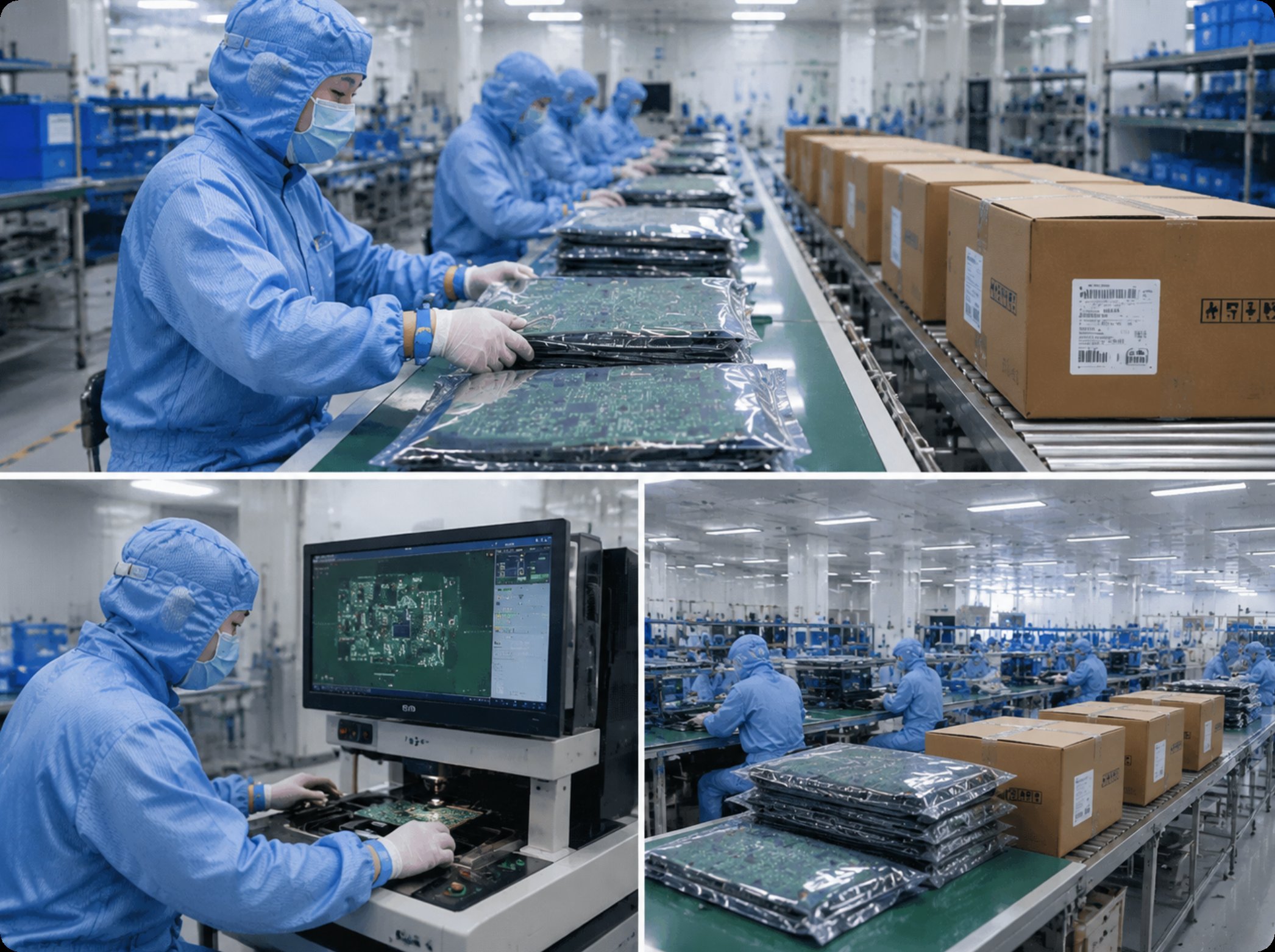

SMT Assembly, Aging Test and Custom Smart Home PCBs: Installing a Line That Is Ready Before the First Board
A smart home board punishes an unprepared line faster than almost any other product a contract factory handles. It mixes radio modules and mains-level relay sections on one substrate, it carries plastic-adjacent components that dislike heat, and it usually arrives as a custom job — a customer's own layout, their own panel, their own firmware — rather than a stock build. When a buyer visits a facility that offers our SMT assembly services, the useful question is not whether the machines exist, but whether the line has been installed and proven for that specific board before the first production panel touches a conveyor. This guide walks through the installation sequence we run for custom smart home programs, from stencil and fixture setup through the aging rack, so that the first day of production looks like the tenth.
Why a Connected Product Punishes a Late Setup
A generic 2.4G gadget board forgives a lazy setup; a smart home panel rarely does. The product combines a wireless module with an antenna keep-out zone, often a capacitive touch layer, sometimes a triac or relay section switching real loads, and a housing that was designed around specific connector heights. Each of those constraints turns into a physical setup decision somewhere on the line: stencil thickness, feeder positions, oven zone temperatures, and how boards travel into the burn-in area. Installing these elements in the right order — and recording each one — is what separates a factory that can quote a smart home project from one that can finish it. The sequence below is the one our engineers follow, and buyers are welcome to ask for the records of any step during an audit.
Step One: Stencil, Fixture and the Panel Map
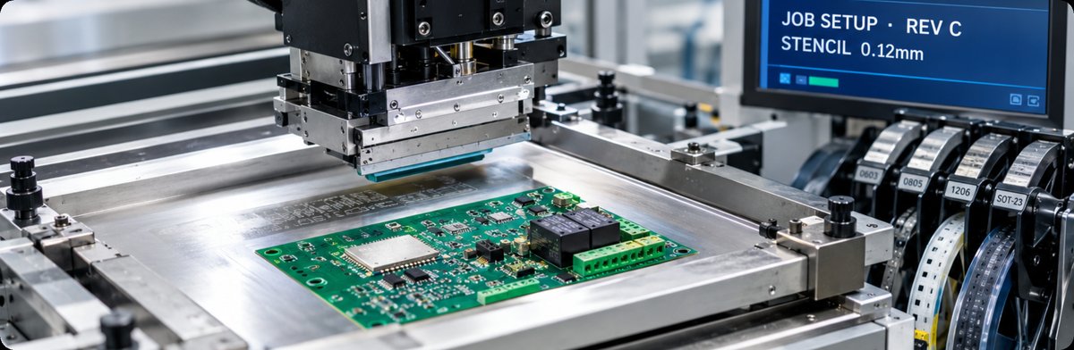
Installation starts before any machine is powered, at the panel level. The customer's layout arrives as a panel; our job is to mount the matching stencil and confirm the frame tension, then fixture the conveyor rails and support pins to the panel's underside so that no flex happens under the printer or the placer. Smart home boards complicate this step with mixed topography — a touch pad on one side, a heavier relay block on the other — so the fixture map is written down, photographed, and filed with the project. When a program repeats quarterly, the fixture comes back off the shelf in minutes instead of being rebuilt from memory. Buyers who send a second variant of the same product benefit most here: the second stencil drops onto a line that already knows the family. Stencil thickness itself is part of the record, because a panel that mixes a fine-pitch module with a few large pads rarely suits a single foil, and the compromise chosen — with the paste release it implies for each footprint — is documented rather than guessed.
Step Two: Feeders, Programs and Component Verification
With the panel fixed in place, the placer is installed with its feeder complement. For a smart home build this means reconciling three lists that rarely agree on the first pass: the customer's bill of materials, the label on each reel, and the data sheet behind both. Feeders are loaded by station number, the pick-and-place program is run in verification mode against a bare panel, and mismatches — a reel of one tolerance where the program expects another — are caught while they cost minutes instead of panels. The verification pass also protects the radio section of the board: an antenna keep-out zone is checked against the placement file so that no shield or connector drifts into ground plane territory. This is also the point where a build that needs through-hole parts, such as a screw terminal for mains wiring, is flagged to move downstream rather than being forced into the SMT flow. Moisture-sensitive parts get their own gate here: reels that exceeded floor-life exposure are baked before loading, and the bake log travels with the program, because a popcorned module shield is a defect that aging would eventually catch anyway — at a far less convenient moment.
Step Three: The Reflow Profile and Its Limits
The oven is installed for the specific board, not for the factory's average board. A smart home panel with a touch layer, a plastic-friendly connector family, or a pre-programmed module has a lower tolerance for peak temperature than a plain industrial control board, so the reflow profile is measured with a instrumented sample board rather than assumed from a paste datasheet. Zones are set, the conveyor speed is fixed, and the measured curve is kept with the project file. Two installation habits matter here. First, the profile is re-measured whenever the panel changes, even for a minor revision, because a moved relay footprint changes thermal mass. Second, the oven's cooling zone is treated as part of the profile, since warpage in a thin smart home panel usually appears as the solder solidifies, not while it is molten.
Step Four: Wiring the Aging Rack Into the Flow
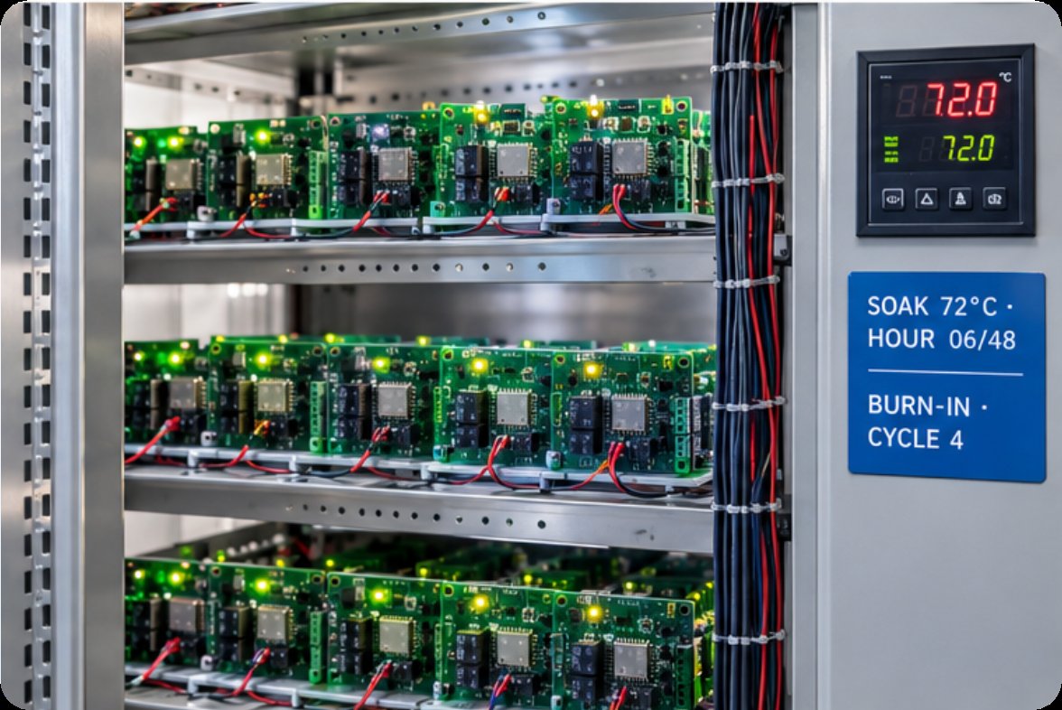
A rack built for our aging test services is not an afterthought at the end of the line; it is installed as a station with its own fixtures, power plan and firmware-loading routine. For smart home boards, aging is where the parts that survive reflow but fail in the field are exposed — a marginal capacitor, a cold joint under a module shield, a relay that chatters under sustained load. Our installation step fixes how boards enter the rack (fixture or tray), how long they soak at elevated temperature, how many are powered and cycling versus merely heated, and what gets logged. Powered slots cycle the radio and the relay section the way a hallway would: pairing attempts, load switches, and repeated reconnects, which is precisely the duty pattern a quiet warm shelf never exercises.
Step Five: First Article Confirmation and Release
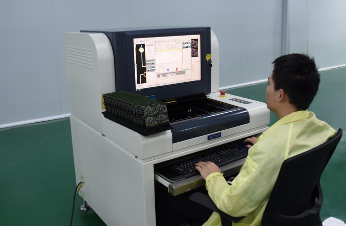
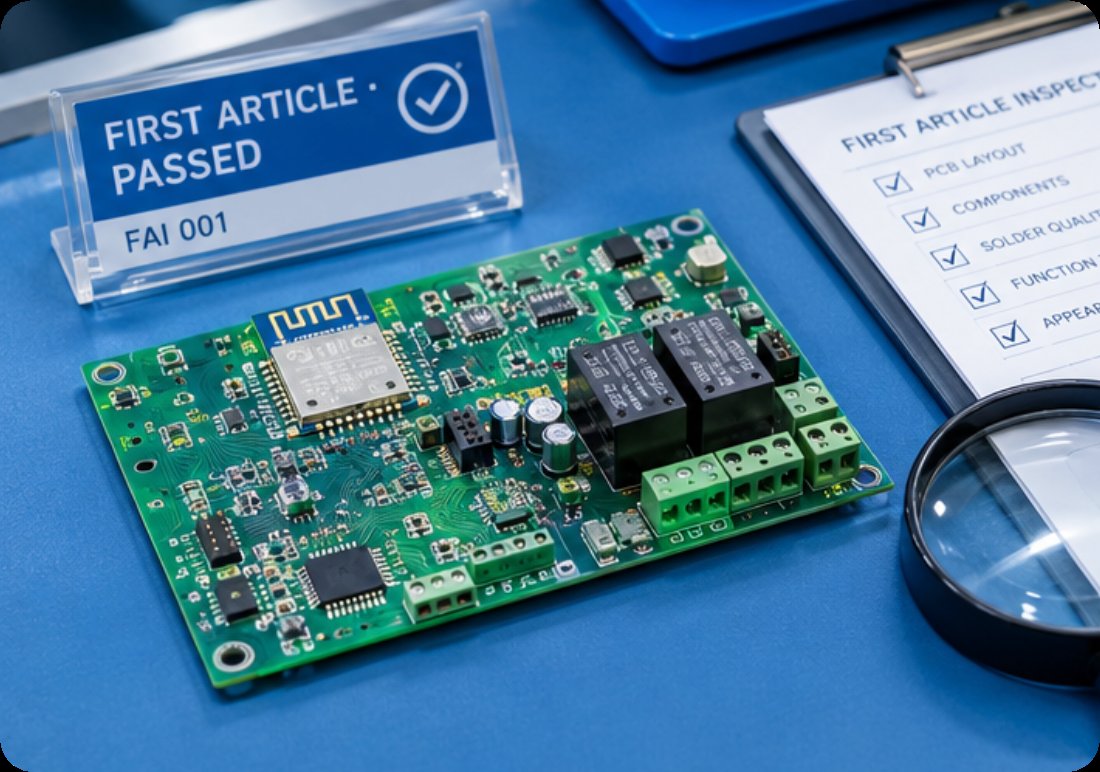
The last installation step is procedural rather than physical. Before volume runs, one panel travels through the complete installed line — print, place, reflow, inspection, and a slot on the aging rack — and the result is measured against the customer's drawing. Solder joint quality, component offsets, and the behavior of the firmware-loaded sample are recorded and signed off. Only then is the line considered installed for that program. The first-article panel also gives the customer something concrete to review: photographs of the actual joints, the measured reflow curve, and the aging log for the sample, rather than promises about how the line generally behaves. A buyer who cannot visit in person still receives the same file an on-site auditor would see, which keeps the sign-off meaningful across time zones.
What Each Step Hands to the Next
| Step | What Is Installed or Fixed | Record Kept for the Program |
|---|---|---|
| One — Stencil and fixture | Foil tension, rail width, support pins | Fixture map, photographs |
| Two — Feeders and programs | Reel positions, placement verification | BOM reconciliation, bake log |
| Three — Reflow profile | Zone temperatures, conveyor speed | Measured curve on an instrumented panel |
| Four — Aging rack | Fixtures, powered duty cycle | Soak time, cycling pattern, log format |
| Five — First article | One full pass through the chain | Signed measurements, joint photographs |
The five steps are not a checklist so much as a chain of custody. The panel map from step one defines what the feeders in step two must hold; the verified program defines what thermal mass the oven in step three must handle; the profile defines which joints the aging rack in step four should be watching; and the first article in step five proves the whole chain on a real panel. When a smart home program jumps from prototype to seasonal volume, the chain is what keeps the second batch consistent with the first, because every physical setting was written down the day it was made. The written chain also shortens every conversation that follows: a revision review starts from records instead of recollections, and a new engineer inherits decisions with their reasons attached.
Bringing Your Program to This Sequence
For a buyer planning a custom smart home product, the installation sequence is a fair set of questions to ask any partner. Which fixture will this panel use, what does the verification pass catch, how is the reflow curve measured, what does the aging rack do to a powered board, and who signs the first article? A factory that offers integrated EMS electronic manufacturing answers those with records; one that assembles answers with adjectives. The same discipline extends to the parts of a build that fall outside pure surface mount — odd-form components and final housing fit are handled by our DIP assembly services, and the connectivity choices behind the product are covered on our smart home PCBA services page. Bring the panel, ask for the chain, and the first production day will behave like every one after it.
Tags: SMT assembly / custom smart home PCB /
Prev: Shell Mold, PCBA Three-Proofing Paint and PCB Fabrication: The Builds Between a Sample and a Launch
Next: No more...