
When Surface Mount Is Not Enough: A DIP Assembly Case Study from an Industrial Controller Line
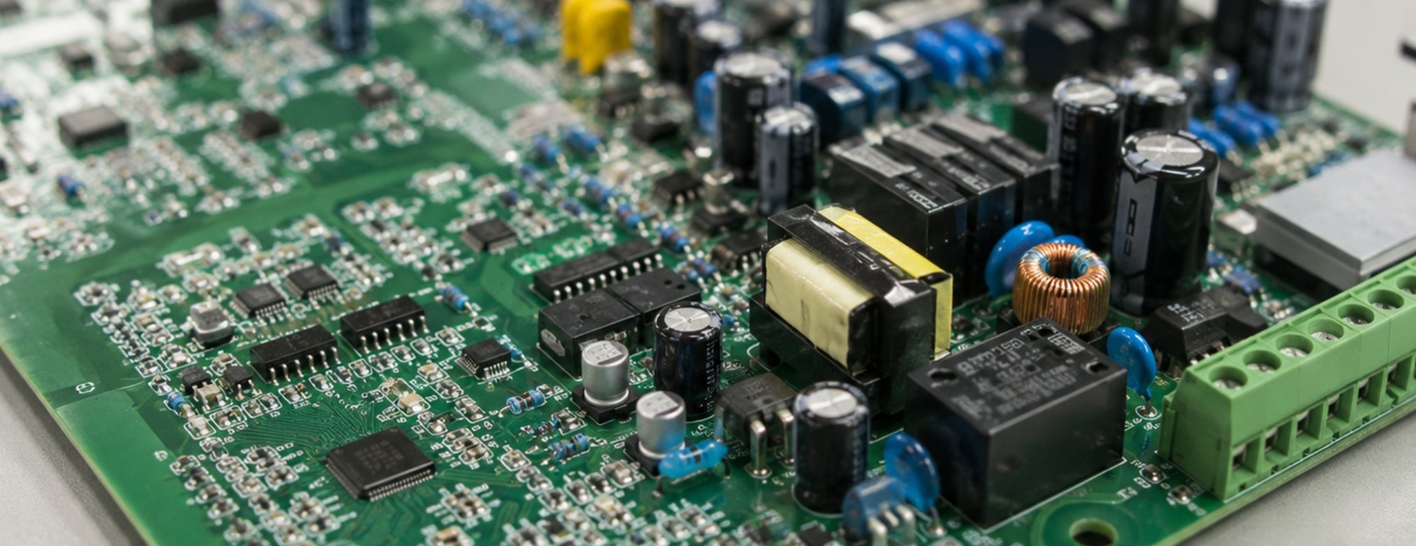
A customer came to us with an industrial motor controller that had already failed two pilot runs at another shop. The board was not complicated by component count — about four hundred parts — but it mixed two very different assembly worlds on the same substrate. The logic side was almost entirely surface-mount and behaved perfectly on any modern line. The power side carried electrolytic capacitors, a toroidal transformer, a relay, and two screw terminals that could not be reflowed at any temperature that would not cook the plastic housings. Every defect in both pilot runs sat on the through-hole side. This is how we rebuilt the process around that constraint.
Why One Process Cannot Cover Every Component
Surface-mount assembly is the default for good reasons: it is fast, dense, and highly repeatable under reflow. But a reflow oven assumes every part can survive the profile, and a meaningful share of power and interface components cannot. Large electrolytics dry out, transformer bobbins deform, and connector housings lose their retention force. Those parts need to be inserted into plated through-holes and soldered from the underside, which is a physically different operation from reflow and usually happens after it.
The consequence is that a mixed-technology board is really two builds sharing one substrate, and the second build can quietly damage the first. Our through-hole assembly service exists precisely for the second half of that sequence, and the case below is a fairly typical example of where it goes wrong when it is treated as an afterthought.
The Board That Broke a Clean SMT Line
The two failed pilots shared the same failure signature. The reflow side was clean — first-pass yield above ninety-nine percent on the surface-mount joints. Every defect sat on the through-hole components, and it clustered in three places: insufficient solder fill in the barrel of the larger capacitor holes, bridges between the relay pins, and cold joints on the screw terminals where the copper area pulled heat away faster than the iron could supply it.
The root cause was not operator skill. The board had been run through a full wave with no selective masking, which meant the underside — already populated with surface-mount parts from the first pass — was exposed to a solder wave it did not need. The wave flooded pads it should never have touched, and the through-hole barrels still did not fill because the heavy copper planes underneath acted as a heat sink. The SMT placement work was fine; the board layout and the soldering strategy were fighting each other.
Planning the Sequence: Reflow First, Then Through-Hole
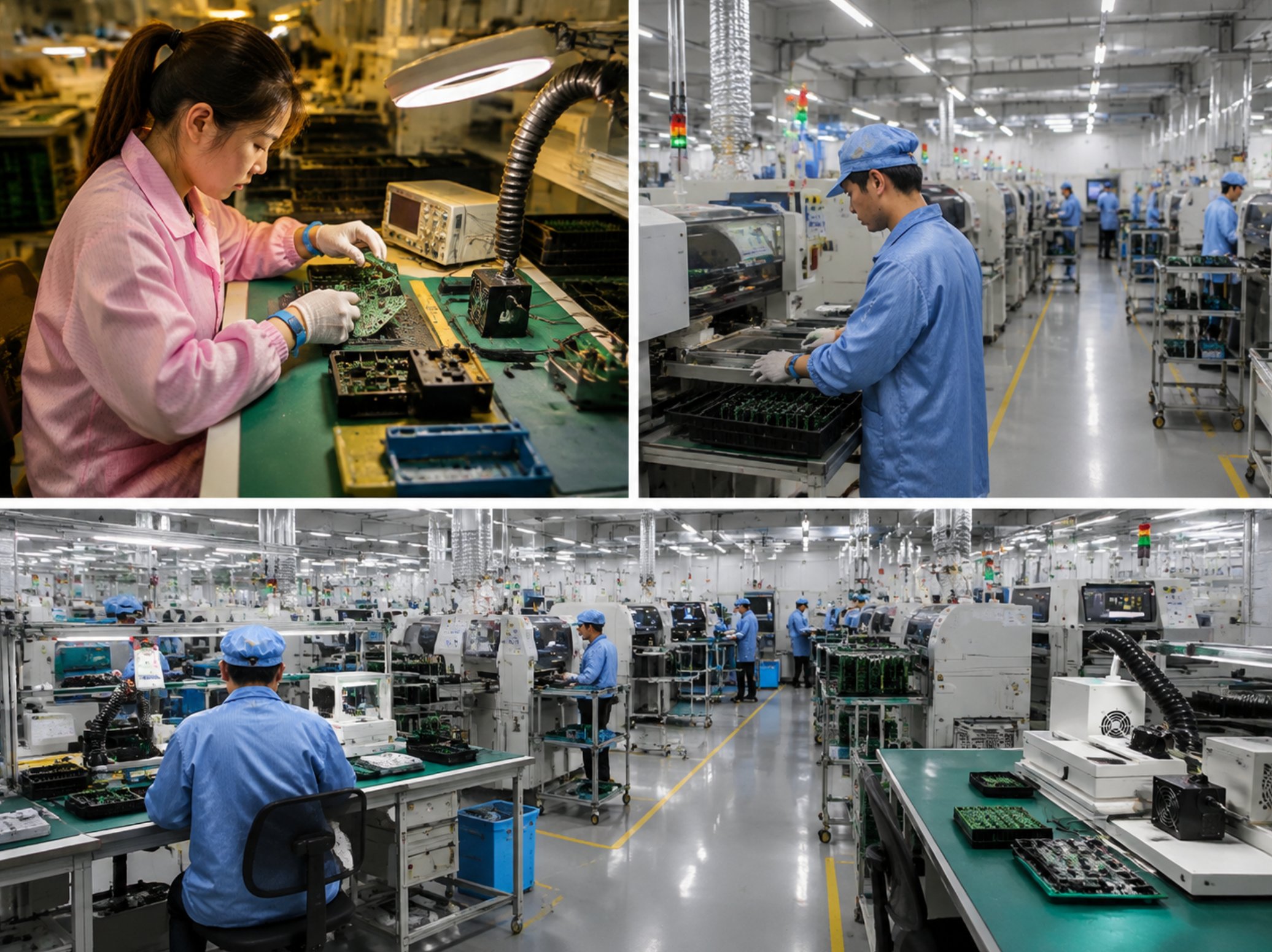
The fix started with the order of operations, which was already correct but was not being respected in the fixtures. Surface-mount reflow runs first and the board cools fully. Only then do the through-hole components go in. In our build we re-pinned that sequence with a physical hold point between the two stages, so a board cannot reach the insertion bench until the reflow record for that panel is closed.
The second change was pre-heating discipline. Through-hole barrels surrounded by large copper planes need the board at temperature before solder is applied, or the joint freezes before the barrel fills. We set a bottom-side pre-heat stage ahead of the soldering operation and verified it with a thermocouple on a sacrificial board rather than trusting the dial. That single measurement moved the capacitor barrel fill from sporadic to consistent.
Fixtures, Masks, and the Selective Solder Decision
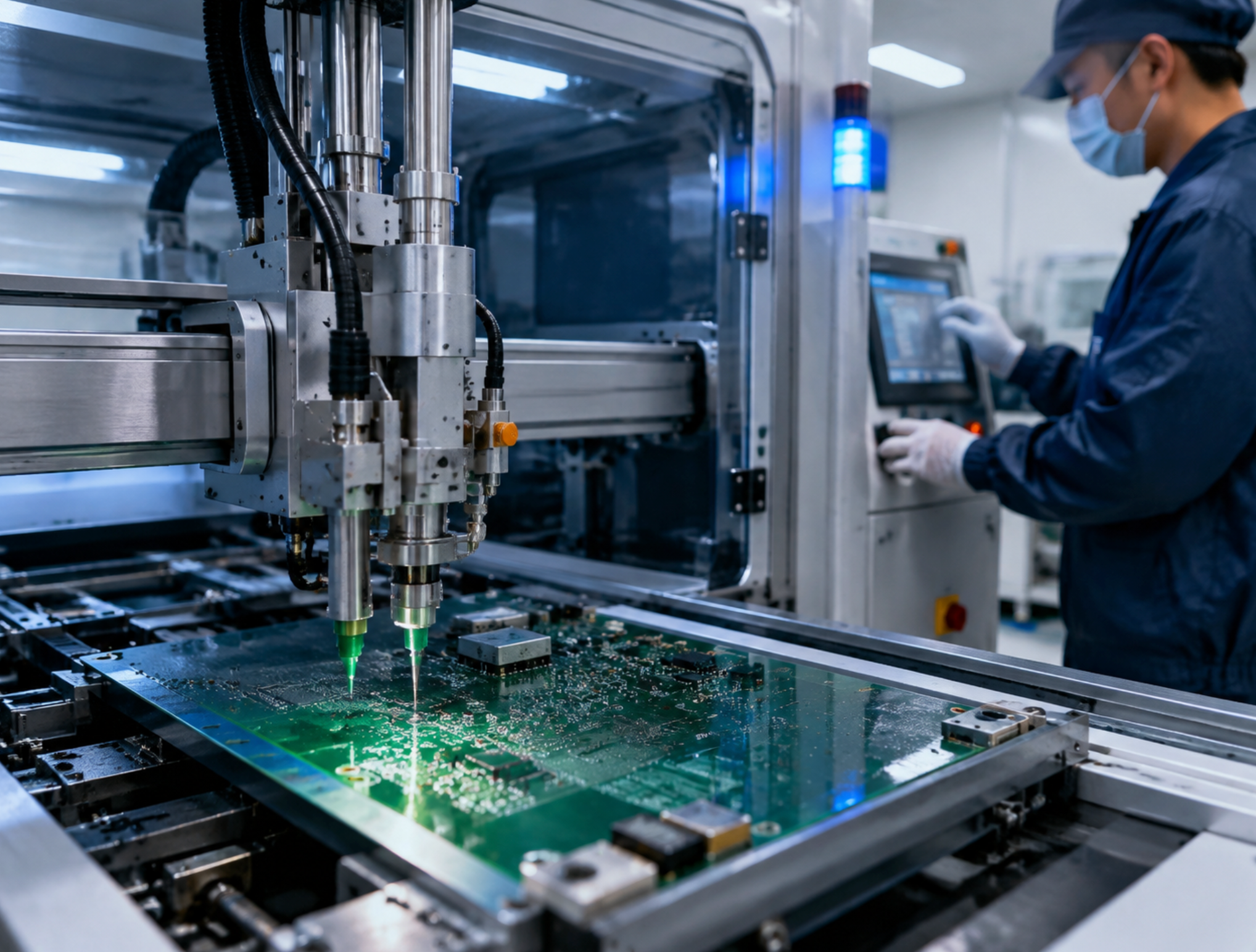
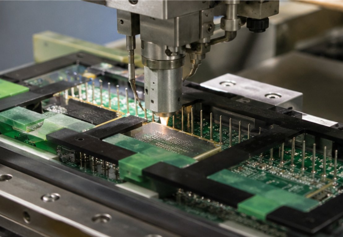
The largest decision was how to apply solder to the through-hole side without touching the surface-mount side. Two options were on the table: a selective soldering nozzle that addresses each joint individually, or a wave fixture with a mask that exposes only the through-hole pads. For this board's mix — roughly sixty through-hole joints spread across a large area, including several heavy terminals — the selective approach won on quality and lost slightly on cycle time, which the customer accepted because the board is built in batches rather than at consumer volumes.
The relay, which had bridged in both pilots, was the clearest beneficiary. A selective nozzle applies flux and solder to the pin group under a controlled dwell, and the bridged pins stopped appearing entirely once the dwell and pull-away speed were dialled in on a test coupon. The screw terminals were handled separately with a hand soldering step under a documented profile, because their thermal mass and mechanical stress make them poor candidates for any automated nozzle.
Inspecting What Reflow Never Shows
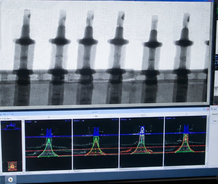
Through-hole joints fail in ways surface-mount inspection is not designed to catch. The relevant measure is barrel fill — how completely solder has risen through the plated hole — and the target under IPC class two work is generally seventy-five percent of the barrel height for a through-hole joint on a board of this type. The failed pilots were averaging well under that on the larger capacitors, which is a latent reliability problem rather than an immediate open circuit.
We verified fill on a sample basis with X-ray rather than visual inspection alone, because a joint can look acceptable on the underside while the barrel remains starved. Visual inspection stayed in the flow for bridging and wetting, but the fill decisions were made on X-ray images from the first articles of each batch and then held with periodic sampling. This is the inspection step most mixed-technology builds skip, and it is the one that catches the failure before the board ships.
What the Numbers Looked Like After the Change
| Metric | Before (two pilot runs) | After the process change |
|---|---|---|
| Surface-mount first-pass yield | 99%+ (unchanged) | 99%+ (unchanged) |
| Through-hole barrel fill (large caps) | Below target, inconsistent | Consistently above 75% |
| Relay pin bridging | Present in both runs | Eliminated |
| Screw terminal cold joints | Recurring | Removed after documented hand profile |
| Rework hours per batch | High | Reduced to isolated touch-up |
Nothing about the surface-mount side improved, because nothing about it had been broken. The entire gain came from treating the through-hole stage as a process with its own parameters rather than a finishing step bolted onto a surface-mount line.
Is a Mixed-Technology Build Right for Your Product
If your product carries connectors, large capacitors, transformers, or anything that cannot survive a reflow profile, you are already building a mixed-technology board — the only question is whether the process admits it. The costs show up as rework hours and field failures rather than as a line item, which is why they are easy to under-estimate during quoting. The boards worth reviewing early are the ones with heavy copper, large thermal masses, or through-hole parts sitting close to fine-pitch surface-mount components.
One practical test: ask your assembly partner how they verify barrel fill. If the answer is visual inspection only, the through-hole joints on your board are being judged on the underside while the barrel itself goes unchecked. On a power board that is where the latent failures live.
Talk to Us About Your Board
We build mixed-technology boards every week, and the through-hole stage gets the same process discipline as placement — documented profiles, dedicated fixtures, and X-ray verification on the joints that matter. If you are planning a build with through-hole content, our PCB fabrication and SMT assembly pages describe the upstream stages, and our electronics manufacturing services team can review your board file before you commit to a pilot. For builds that continue into box assembly, the final product assembly stage closes the loop on the same line.
Tags: DIP through-hole soldering / selective wave / barrel fill X-ray /
Prev: Measured ESD Protection Data: How We Keep SMT and Industrial PCBA Defect-Free
Next: How Smart Home PCBs Learned to Survive the Bathroom: A Conformal Coating Story