
Shell Mold, PCBA Three-Proofing Paint and PCB Fabrication: The Builds Between a Sample and a Launch
Automotive electronics programs do not move from a finished design to mass production in one step, and the contracts behind them are written as if everyone already knows this. A Tier-2 supplier bidding for a vehicle control board is asked to pass a sample build, a design validation build and a production ramp build — three separate rounds of hardware, each with its own purpose, its own failure modes and its own paperwork. The case examined here follows a body-control module program through those rounds at Newei, and the pattern that emerged is useful for any team planning an automotive PCBA project: each build exists to eliminate one class of problem, and the service that anchors each round changes accordingly. PCB fabrication carries the sample round, shell mold work carries validation, and conformal coating decides whether the ramp stays stable. Treating the three builds as one continuous blur is the most common reason programs slip a quarter.
Why Automotive Boards Cannot Skip a Build
Consumer electronics can iterate in the field. A car cannot. A control module that fails in service may sit inside a dashboard for years, and the recall mathematics behind that reality is why automotive customers demand qualification evidence at defined points instead of trusting a final inspection. A field return is not just a warranty claim; it is a documented event that the automaker traces back through build records, and a supplier whose records end at final test has nothing to show. Qualification batches exist so that every failure mode discovered later can be traced to a round where it was either caught or never tested. Each build is therefore not a formality but a filter with a job: the sample build proves the design can be manufactured at all, the validation build proves the design works inside its intended housing under real conditions, and the ramp build proves the process holds when volume multiplies. Skipping or merging rounds does not save time — it moves the discovery of a problem to a stage where it is more expensive to fix. In this program, the customer arrived with a compressed schedule and considered combining the first two rounds; the build plan below is what preserved both the schedule and the evidence trail the automaker required.
The Sample Build: Where the Board Tells the Truth
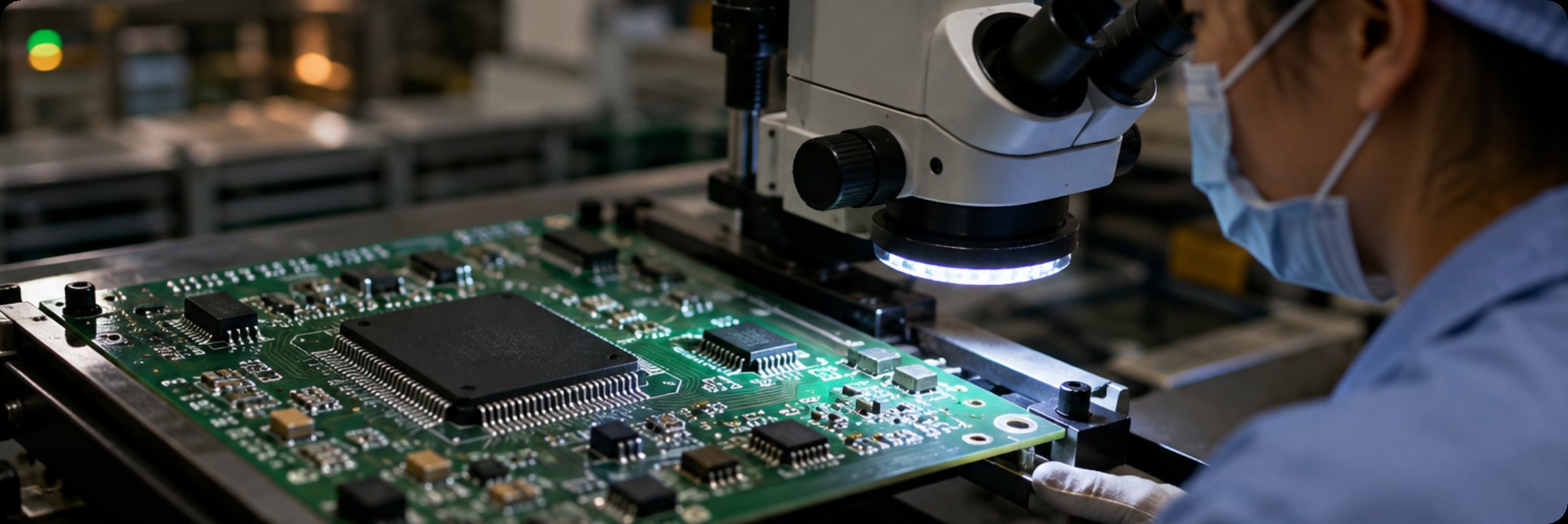
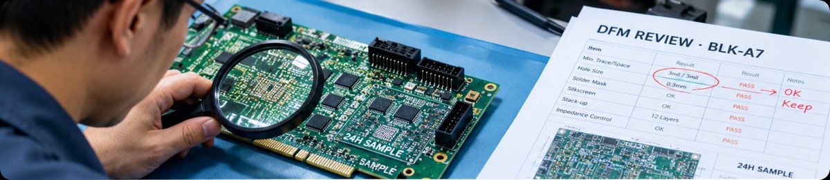
The sample round began with bare boards, and the first decision was how to make them. The program needed multilayer boards with controlled impedance and blind via structures, and the schedule allowed days rather than weeks. Fast sampling under 24 hours turned the board into a testable artifact almost immediately, but speed alone was not the point. The sample build exists to surface design errors while they are still cheap, so the free DFM review attached to the fabrication run mattered more than the turnaround: layer stackup recommendations, solder mask openings that would not survive etching tolerance, and annular ring sizes that assumed a drilling precision the fab could not hold. Copper weights, surface finish and trace geometry all interact: the boards in this program carried 3mil line-width regions for a dense connector fanout and gold-finger edges for the diagnostic interface, and both features behaved differently on a shared panel than on a dedicated run. Fabricating each revision as a separate sample run rather than combining it with other customers' panels kept the verification clean — combined-panel production is cheaper per square meter and introduces shared-process variables that make a failed sample impossible to diagnose. The trial production report that came back with the boards became the first document in the qualification file.
The Validation Build: Where the Housing Meets the Board
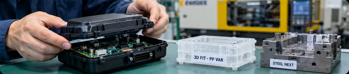
Once the board passed its sample gates, the validation round asked a different question: does the assembly fit the world it will live in? This is where shell mold work dominates the agenda. The housing for the module was specified in glass-filled nylon for heat deflection, with a polypropylene variant explored for a cost-down option, and validation hardware had to reflect both. Rapid 3D-sampled enclosures arrived before the steel mold was cut, which allowed the uncomfortable discoveries to happen in plastic: a connector boss that fouled the wire harness route, snap-fit tabs whose deflection exceeded the resin's capability at dashboard temperature, and a wall section that created a visible sink mark opposite a high-voltage pin. Each discovery fed back into the mold design before tooling investment locked it in. By the end of the validation build, the enclosure and the board assembled without rework, and the mold moved to steel with its parting line, gate locations and ejection layout already proven — which is precisely the risk a mold carries that a circuit board does not.
The Ramp Build: Where the Coating Becomes a Process
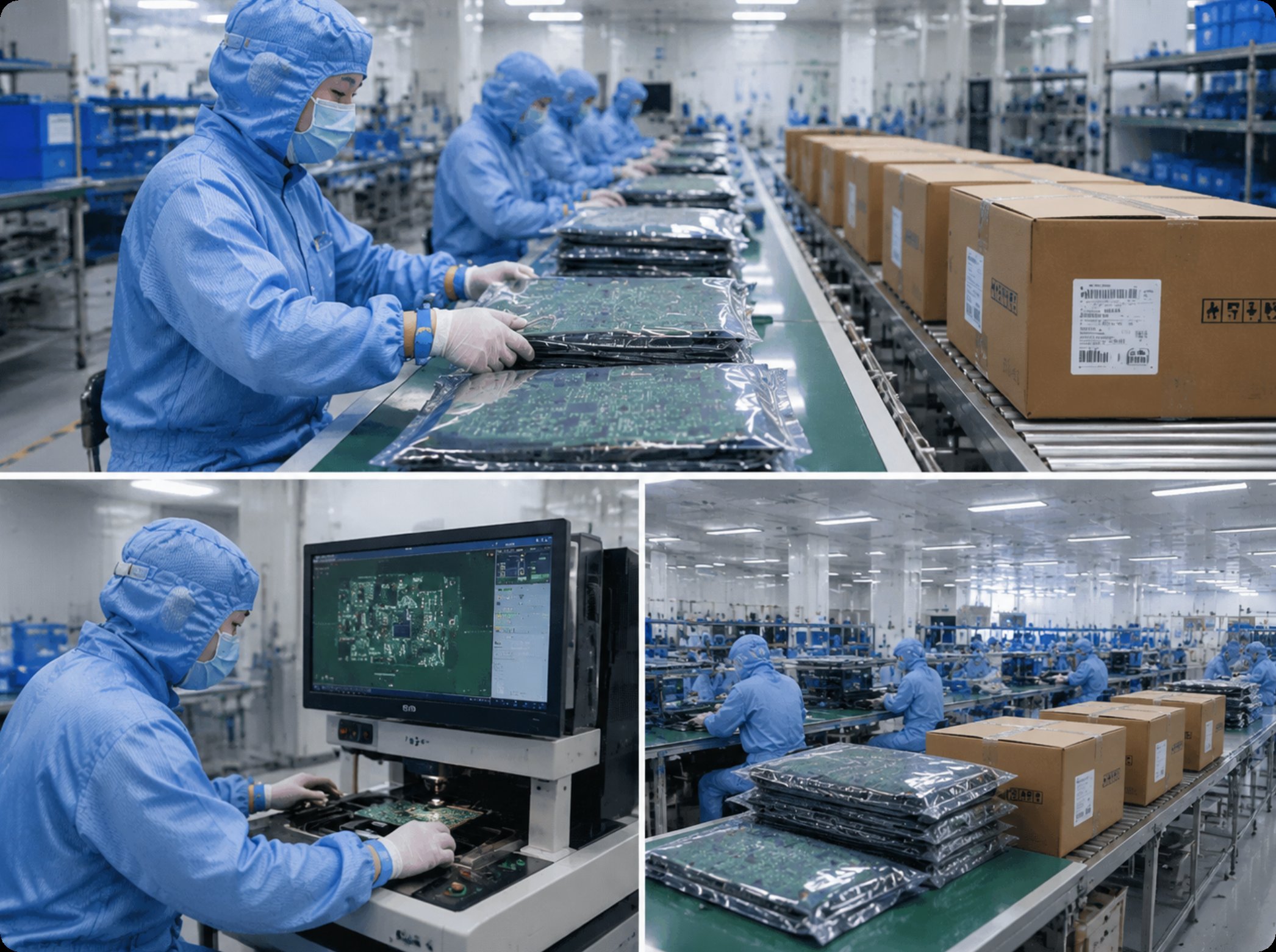
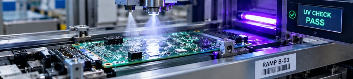
The production ramp introduced the third filter: environmental durability at volume. The module operates where moisture, dust and vibration arrive together, so the conformal coating step stopped being a finishing touch and became the process that defined yield. Manual coating, which this customer had used at the prototype stage, could not hold the consistency the ramp demanded — brushed films vary in thickness, and thin spots over board edges become the corrosion sites that fail two winters later. The dedicated spraying line changed the character of the step: automated application across two spray systems, UV inspection to verify coverage before cure, and controlled baking to fix the film. The coating's job list is long — insulation, moisture resistance, dust exclusion, anti-corrosion and vibration damping in one transparent layer — and every item on it is only as real as the coverage map. Cure parameters were frozen alongside coverage, because a film that insulates when correctly baked can craze when cured hot and fast to save line time. During ramp, the UV records became the evidence that every board in every shipping carton carried the same protective film, which is what the automaker's auditors actually wanted to see.
What Each Build Eliminates, Side by Side
The division of labor across the three rounds is easiest to audit as a table. Each build eliminates the class of problem that becomes unaffordable one stage later, and each produces a specific artifact that survives into the program file.
| Build Stage | Problem Class Eliminated | Evidence Artifact | Anchoring Service |
|---|---|---|---|
| Sample build | Stackup, impedance and manufacturability errors in the bare board | Free DFM review and trial production report | PCB fabrication (1-36 layers, HDI, blind and buried vias, 3mil trace) |
| Validation build | Housing interference, material selection and assembly defects | 3D-sampled enclosure fitting records ahead of steel tooling | Shell mold (nylon, polypropylene, PEI, stainless; no MOQ) |
| Ramp build | Environmental failures from inconsistent protection | UV coverage inspection and cured-film records per batch | Three-proofing paint line (automated spray, UV check, baking) |
The Cost of Merging Builds
The temptation in every compressed schedule is to collapse rounds, and the arithmetic behind that temptation deserves honesty. Merging the sample and validation builds saves a few weeks on paper and costs a mold revision in practice: enclosure changes discovered late force steel rework, and steel rework has a lead time no expedite fee can compress. Merging validation and ramp has the opposite failure signature — process problems that validation would have absorbed arrive instead at full volume, where each rejected batch carries the price of already-molded housings and already-assembled boards. The program in this case held the three rounds apart and still met the launch date, because the rounds were planned in parallel where possible: mold design began while sample boards were in fabrication, and coating process trials ran on validation hardware. The rule the program followed was simple: a build may start early, but it may not close until its predecessor's artifacts are signed. What was never parallelized was the evidence — each gate closed with its own artifacts before the next round's spending began.
Handover Notes for the Next Program
The program ended with a launch and a qualification file thick enough that the follow-on variant skipped no gates — the customer simply reused the structure. That is the practical legacy of separating builds: the file becomes a template. If you are planning an automotive or industrial control board and want the same build discipline, the automotive electronics PCBA program page outlines how the rounds are staged, and the underlying services are documented individually: PCB fabrication for the sample round with its free DFM review, shell mold services for validation-stage housings in engineering resins, and the PCBA three-proofing paint line for ramp-stage protection with UV-verified coverage. For the assembly steps between fabrication and coating, see learn more about our manufacturing capabilities, and for the full service scope across the factory, our electronics manufacturing services page ties the sequence together. A program that respects the builds between sample and launch buys the only thing an automotive customer actually audits: evidence that nothing was discovered one stage too late.
Tags: PCB fabrication / shell mold / three-proofing paint /automotive PCBA /
Next: No more...