
Custom Automotive Electronics and Shell Mold: Reliability Data from a Sealed-Build Validation
A fleet telematics OEM came to NEWEI with a board that had already passed its electrical tests, a housing that existed only as a CAD file, and a launch date that did not move. The device was a commercial-vehicle terminal that would sit on a truck dashboard for ten years, and the OEM had learned the hard way that bench-passing a PCB is not the same as surviving a validation run with the enclosure fitted. What they asked for was not more test time. It was a single measured program across three NEWEI services working as one build: custom electronic devices PCBA for the assembled board, custom automotive electronics for the vehicle-grade limits, and shell mold for the sealed enclosure that had to pass beside it. This article reports the numbers from that program and what they changed before the first 500 units shipped.
Why the OEM Tested with the Housing Fitted
The OEM's field history showed that most returned units failed not on the PCB but at the boundary where the board met the housing: connector seats, gasket lines, and the seam where two shell halves closed. A bench test never sees those boundaries because a bench test has no enclosure. The program therefore treated the housing as a first-class test subject rather than a cosmetic cover, and every measurement below was taken with the sealed unit assembled, not with an open board on a lab cart.
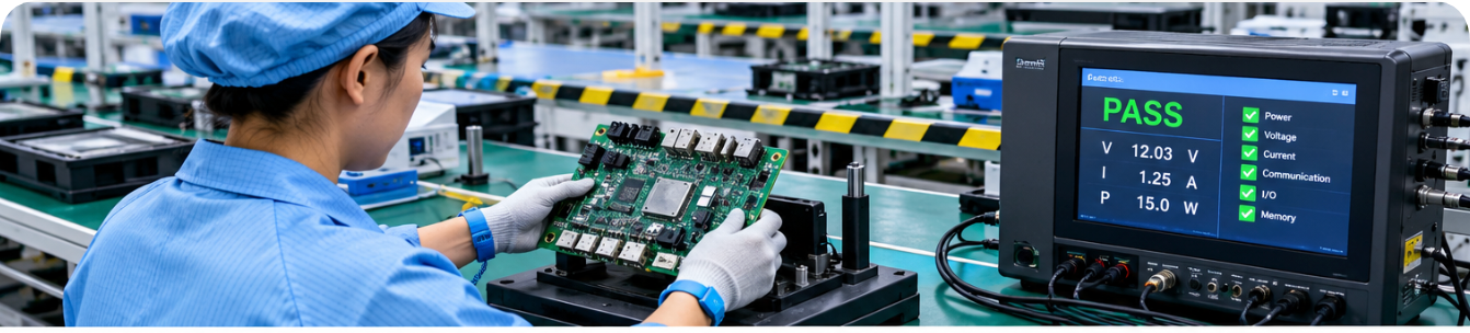
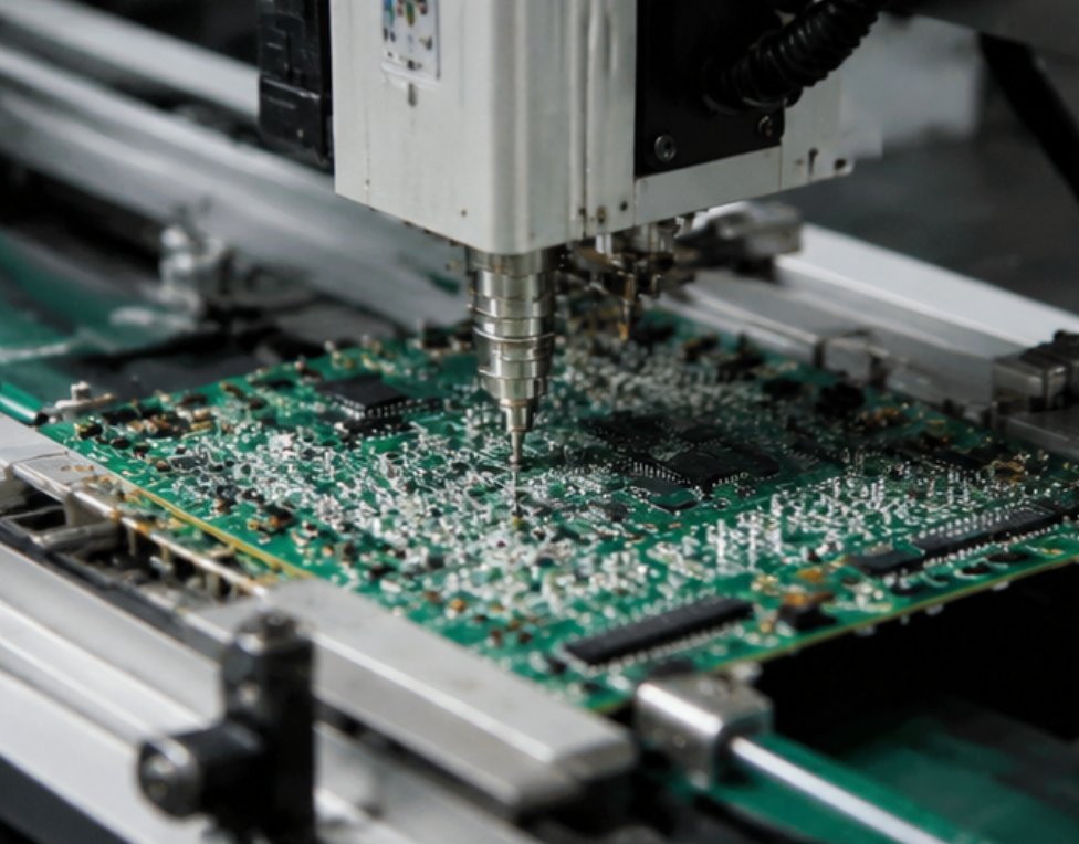
The assembled board above was built on the custom electronic devices PCBA line and went through its first electrical test before any chamber work began, which gave the team a clean baseline for everything measured later inside the sealed unit.
Test Profile and Acceptance Limits Agreed in Advance
All limits were written into a shared matrix before the first unit was built, so neither side could move a goal after a failure. The agreed profile covered temperature cycling from minus 30 to plus 70 degrees Celsius over 300 cycles, random vibration at 3.1 g RMS across 10 to 500 Hz for 8 hours per axis, an IP65 ingress check with dust and a 30-minute water spray, and a 72-hour continuous operation soak at 50 degrees Celsius. The OEM supplied the fleet duty cycle; NEWEI supplied the chambers, the fixtures, and the measurement points.
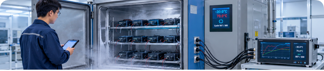
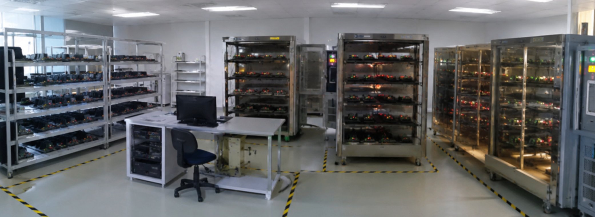
The chamber above held twelve fully assembled units at once, each wired to a live power source so that startup and current draw were recorded at every temperature extreme rather than only after the chamber returned to room temperature.
Thermal Cycling Results at the Connector
Across the 300 temperature cycles, all twelve units started successfully at every cold extreme and every hot extreme, with zero cold-start failures logged. Steady-state current draw stayed inside the agreed corridor for the full run. The more interesting number was the connector margin: contact resistance at the main harness connector rose by only 2.1 percent from the first cycle to the three-hundredth, well inside the 10 percent limit the OEM had set. The measurements confirmed that the PCB manufacturing quality carried through assembly and into the sealed build without a degradation step.
Vibration Exposure and the Resonance Fix
The random vibration run produced a single finding worth reporting. One mounting-boss geometry, which had passed a bare-board sine sweep, showed a resonance peak at 137 Hz once the shell halves were fitted with screws and gasket. The fix was a 0.6 mm rib added to the inner housing wall, and the re-test shifted the resonance above 400 Hz, clear of the fleet excitation band. Because the rib change touched the housing, the sealed-unit electrical check was repeated afterward, and the connector margin result was unchanged. The vibration logs also confirmed that no fastener loosened across the full 8-hour axis run, which the OEM recorded as the mechanical acceptance point.
Ingress Checks after Dust and Spray
The IP65 check was run on the production-representative housing, not on a hand-polished prototype. After the dust chamber and the 30-minute water spray, every unit passed internal inspection with no ingress beyond the gasket line, and the pressure-equalization vent, which had been the failure point on an earlier housing design, held across all twelve units. The two halves showed no dimensional drift after the temperature and vibration exposure, and the overmolded connector boot remained bonded with no separation at the interface. For an enclosure that had never been molded before this program, the first-pass result removed the largest open risk in the OEM's launch plan.
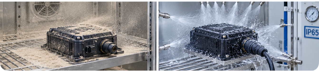
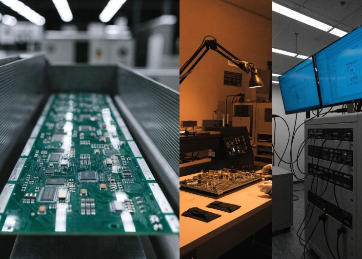
The sealed enclosure above went through dust and water spray after thermal and vibration exposure, so the ingress result reflects a housing that had already been mechanically stressed rather than a fresh sample.
What Changed Before the First Production Batch
The program changed three things before mass production. First, the rib addition went into the shell tooling as a revision, which added two weeks to the mold timeline but removed a resonance that no schedule could have fixed in the field. Second, the OEM's incoming inspection added a 100 percent connector-seat torque check, because the measured contact-resistance drift, while small, was traceable to seat torque variation in the pilot build. Third, the acceptance matrix itself became the template for the OEM's next two programs, since both sides had agreed to every limit in advance and neither side needed to negotiate a failure after the fact. The 500-unit first batch shipped on the original launch date, with the program report attached to the lot file.
Cost and Schedule Impact of Testing the Assembly
Testing with the enclosure fitted added roughly 11 percent to the validation phase cost compared with a board-only run, almost entirely in chamber time and fixturing. In exchange, the OEM avoided what the field history suggested would have been a 4 to 6 percent first-year failure rate from enclosure-boundary faults alone. On a ten-year fleet service life, the trade was strongly positive: one paid validation program replaced what would otherwise have been a rolling series of warranty returns. The OEM's procurement lead summarized the logic in one sentence: an electronics manufacturing services partner that measures the assembled product, not just the bare board, is the only kind worth putting on a truck dashboard.
Applying the Same Matrix to Other Products
The same structure applies to any product where a sealed housing meets a live PCB: the measurement must happen at the seam, with the enclosure fitted, under the real duty cycle. The sequence that worked here was thermal cycling on sealed units first, then vibration, then ingress, then a repeat electrical check after the mechanical exposure. Any product family facing connector-seat failures, gasket-line leaks, or resonance-driven fatigue can borrow the matrix directly, and the same three services carry the program: the board assembly, the vehicle-grade limits, and the molded sealed home described above.
| Check | Profile | Result |
|---|---|---|
| Temperature cycling | -30 to +70 deg C, 300 cycles, sealed units live-powered | Zero cold-start failures; connector contact resistance +2.1% |
| Random vibration | 3.1 g RMS, 10-500 Hz, 8 h per axis | Resonance at 137 Hz fixed by 0.6 mm rib; re-test above 400 Hz |
| IP65 ingress | Dust chamber plus 30-min water spray | All 12 units passed; vent and overmolded boot held |
| Operation soak | 72 h continuous at 50 deg C | Steady current draw inside agreed corridor |
The full results are kept on file with the lot documentation for the first 500 units, and the same matrix is now the reference for the OEM's next two programs. The launch date did not move. For a view of the same measured approach applied to a different boundary problem, the related case study on smart-home PCB survival is the natural next read.
Tags: shell mold /automotive electronics PCBA / IP65 / fleet terminal /
Prev: EMS and SMT Assembly: Five Trends Reshaping the Modern SMT Line
Next: PCBA Three-Proofing Paint and Product Assembly: Compared Across the Last Mile