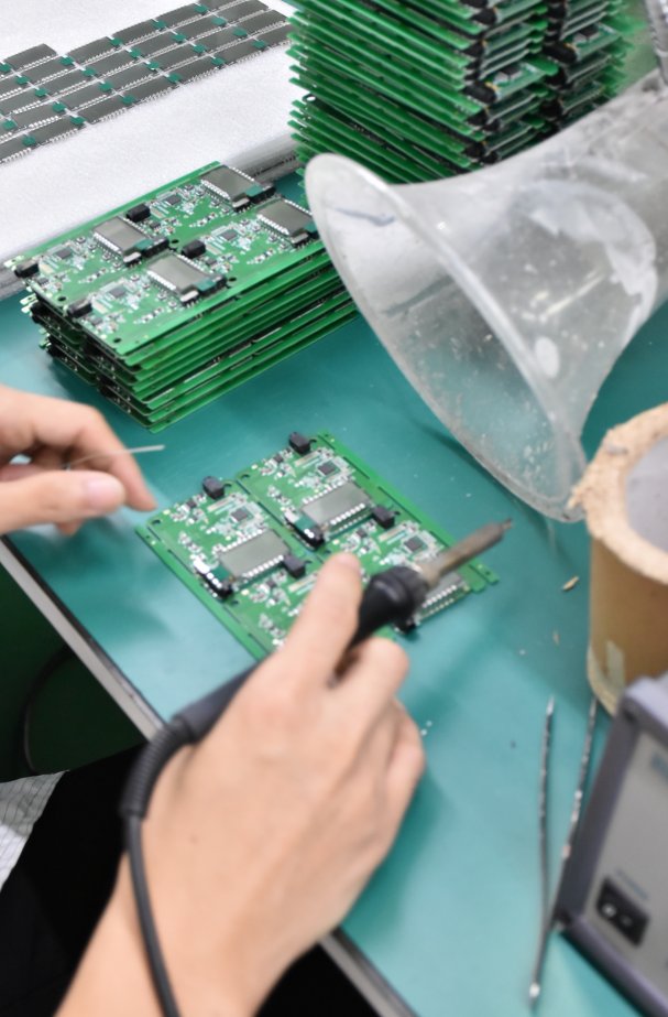

How Smart Home PCBs Learned to Survive the Bathroom: A Conformal Coating Story
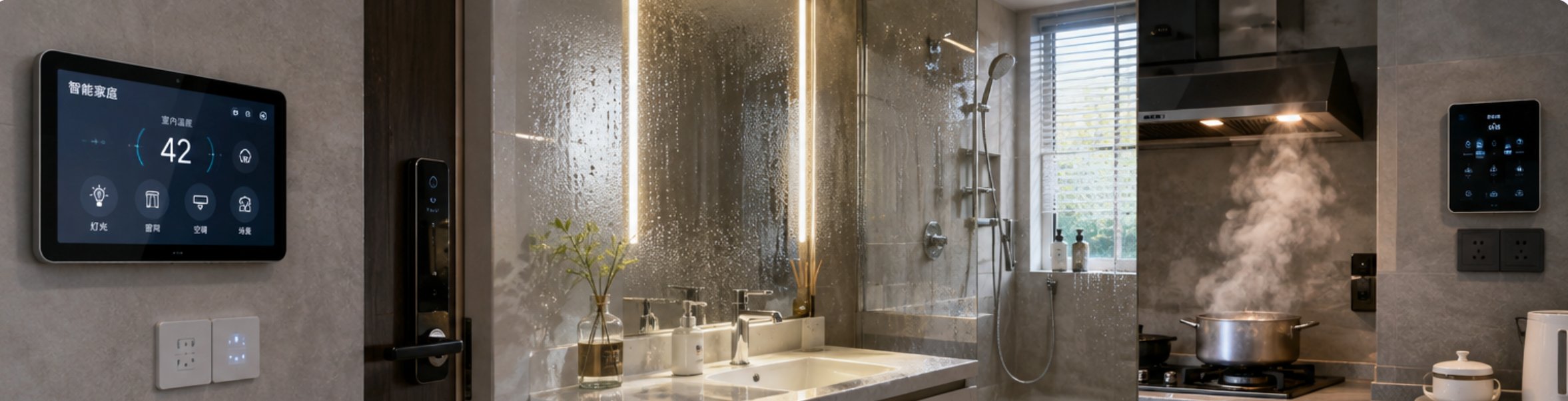
A smart mirror in a bathroom, a control panel above a hob, a lock on a balcony door, a camera under an eave. None of these are outdoor products in the catalogue sense, and all of them live in conditions that a bare assembled board was never meant to survive.
The consumer electronics industry spent a decade assuming that "indoor" meant "dry". Smart home hardware broke that assumption, and the response - moving protection from the enclosure down to the board - is one of the quieter changes in electronics manufacturing over the last few years. Our smart home PCBA work sits right in the middle of it.
🏠 The Assumption That Indoor Means Safe
Conformal coating was, for a long time, an industrial option. It appeared on automotive boards, on outdoor telecom equipment, on anything with a specification that mentioned salt fog. A television remote controller did not need it, and for years that reasoning extended by default to anything sold for the home.
Then smart home products moved out of the living room. The placements that changed things:
Bathrooms - mirrors, scales, ventilation controls, heated towel rails. Cyclic humidity plus temperature swings.
Kitchens - hobs, extractor hoods, smart taps, under-cabinet panels. Cooking oil vapour plus dust plus heat.
Balconies and entrances - locks, doorbells, cameras, parcel boxes. Rain splash, sun, and in coastal markets, salt.
Garages and utility rooms - chargers, meters, pump controllers. Condensation on cold surfaces.
A product can pass a bench test in an air-conditioned lab and fail in eighteen months in a real bathroom. The board did not change; the environment did.
💧 What Actually Kills a Board in a Kitchen
Three mechanisms account for most of the field returns we see, and they behave differently:
Condensation. A device that warms up during use and cools overnight draws moist air in as it cools. Water condenses on the coldest surface, which is often the board. It is not immersion - it is a thin film forming repeatedly in the same places.
Hygroscopic contamination. Cooking oil vapour settles as a slightly conductive film. On its own it rarely causes a fault; combined with dust and humidity it bridges fine-pitch pads.
Electrochemical migration. With a film of moisture and a DC bias between adjacent tracks, metal ions migrate and grow dendrites. This is the mechanism behind failures that appear only after a year or more - it is slow, and it looks random.
The important detail is that all three need a board-level answer. Sealing the enclosure helps with splash and does nothing for condensation that forms inside the box.
🧪 Three Ways to Protect, and Why Two Faded
The industry tried three approaches, and the progression is instructive:
Enclosure sealing. Gaskets, potting, sealed membranes. Effective against splash, expensive, and it fights two other requirements: heat dissipation and serviceability. A fully potted unit cannot be repaired, and a sealed enclosure still traps the humidity that was inside when it was closed.
Full board coating. Dip or spray the whole assembly. Cheap per unit and very effective at keeping moisture off the copper. The trouble shows up at the edges: connectors get coated and stop making reliable contact, test points become unreachable, and every area that must stay clean needs masking anyway.
Selective application. Coat the areas that need it, leave the areas that must not be coated. This is where the industry settled, and it is what our PCBA three-proofing paint service is built around.
🎯 Selective Application and the Masking Problem
Selective coating shifts the difficulty from chemistry to planning. Before the first board is coated, someone has to decide what stays clean:
Connectors and contacts - a coated contact is a failing contact.
Test points - if in-circuit test comes after coating, the points must stay open.
Edge fingers and sockets - anything that mates mechanically.
Buttons, switches, and displays - coating creeps, and creep into a tactile switch is a return waiting to happen.
High-voltage areas - where clearance matters, coating thickness becomes part of the insulation calculation rather than an afterthought.
In practice this means a fixture. For volume runs a masking jig pays for itself quickly; for prototypes, boots and dots applied by hand are slower but work. Either way the decision has to be documented, because the person masking the fifty-first board needs to reach the same conclusion as the person who masked the first.

📋 Where Protection Sits in the Sequence
The most common mistake is treating coating as the last step - something applied after everything else is finished. It is not; it sits in the middle, and it constrains what comes after.
A workable order:
SMT assembly and reflow.
Through-hole assembly, if the design is mixed-technology.
Cleaning - coating over flux residue traps contamination against the board.
Masking, then coating, then cure.
Inspection, and only then final assembly into the enclosure.
Cleaning is the step most often skipped, and it is the one that determines whether coating helps or hurts. A board coated without cleaning is sealed with its contamination still on it.
📊 Failure Modes Before and After
| Failure mode | Bare board in a wet location | With selective coating |
|---|---|---|
| Condensation film on pads | Forms on every cool-down cycle | Blocked from the copper surface |
| Dendrite growth between fine-pitch pads | Common after 12-24 months | Largely suppressed under the film |
| Oil and dust bridging | Progressive, worse in kitchens | Surface contamination, cleanable |
| Connector contact resistance | Normal until corrosion starts | Unchanged, provided masking was correct |
| Rework and repair | Straightforward | Coating must be removed locally first |
| Unit cost impact | None | Coating plus masking; jig amortised over the run |
The last two rows are the honest trade. Coating adds cost and it makes rework slower. It earns that back where the alternative is a field return.

🔮 What to Lock Down Before Layout
The decisions that matter most are made before the board is routed, and they are cheap at that stage and expensive later:
Which zones must stay uncoated - decide it on the schematic, and place connectors and test points so masking is geometrically simple.
Test strategy - if in-circuit test runs after coating, the fixture and the mask are the same problem; if it runs before, the sequence is easier.
Component selection - some parts do not tolerate coating, and some have vents that must stay open. Checking this at selection time avoids a redesign.
Clearance and creepage - where coating is credited as insulation, the thickness and coverage have to be specified, not assumed.
Handled this way, protection stops being a rescue for a failing product and becomes a line item that was planned from the start. Our EMS team reviews these points at the design stage, and our PCB fabrication side flags the finish and solder mask choices that affect coating adhesion. Send us the installation environment and the expected service life - those two answers determine the coating more than the board does.
Tags: PCBA coating / smart home PCB / three-proofing paint / masking /
Prev: When Surface Mount Is Not Enough: A DIP Assembly Case Study from an Industrial Controller Line
Next: What a Mixed SMT and Through-Hole Board Really Costs: An ROI Model for 2026 Builds