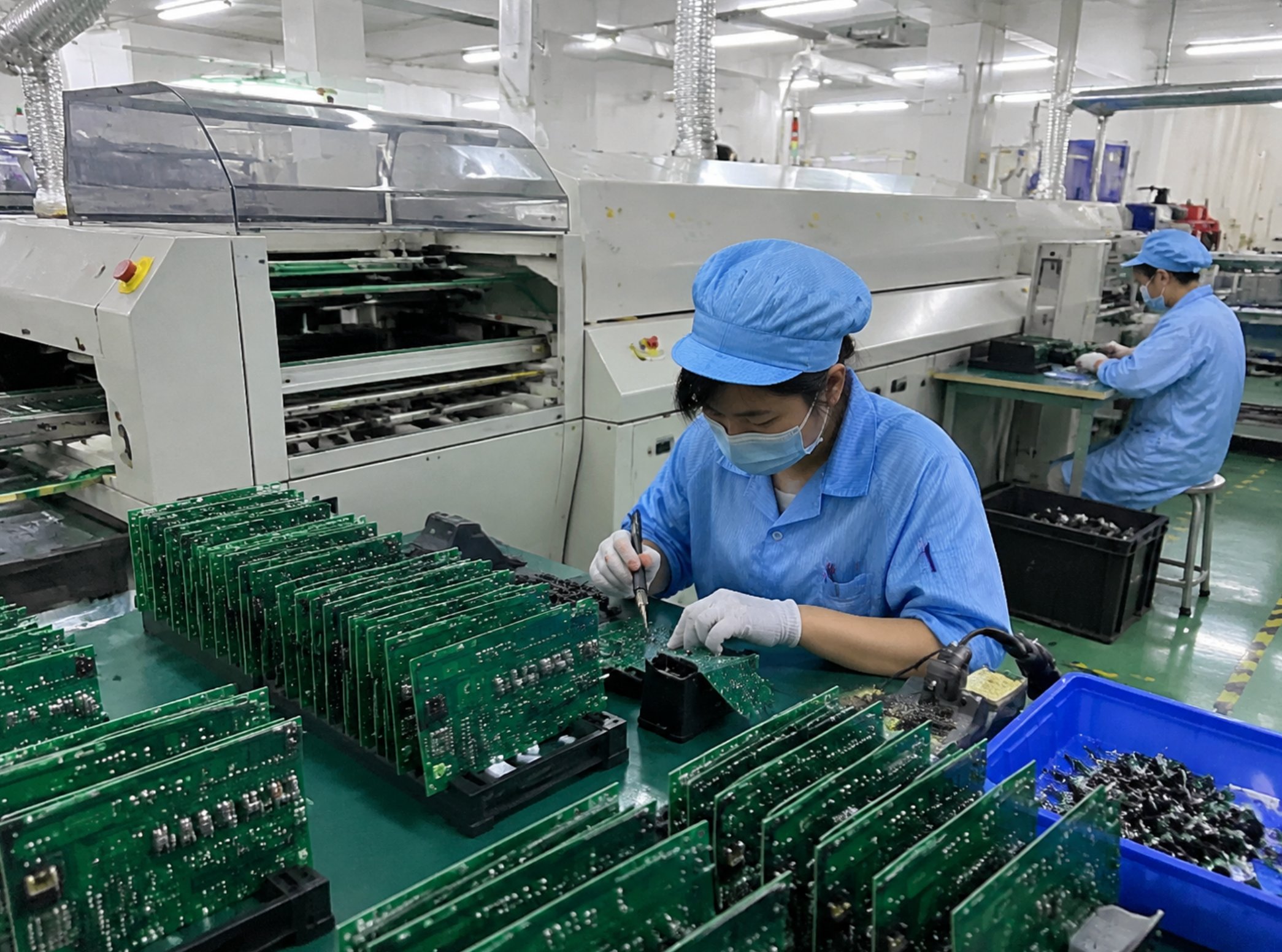

Product Assembly and DIP Assembly: How Far a Late Change Travels
A busy-season production schedule rarely collapses from slow assembly lines. It fails when a minor design correction is approved after multiple departments have already built tooling, documentation, and physical inventory around the previous file version. The critical metric to measure before a peak period is not maximum board throughput, but how much completed work a single design revision invalidates.
Correcting a silkscreen legend costs an afternoon. Shifting a single hole coordinate can discard an entire wave soldering pallet, invalidate a first-article inspection sheet, and ruin a sealed component kit in one morning—even if both appear as simple one-line revisions in an email thread. Managing this operational risk forms the baseline of our Turnkey EMS Electronic Manufacturing Services, ensuring a single unified project file moves across specialized workshops without silent re-interpretation.
This technical review analyzes operational workflow across three core electronics manufacturing phases: PCB fabrication and assembly, DIP through-hole insertion, and final box-build assembly. Rather than ranking processes by theoretical speed, we track how a single downstream revision propagates through factory layers and calculate what physical assets it invalidates at each stage. Where specific parameters vary by custom build specification, we state so plainly; engineered production schedules depend on verified manufacturing constraints rather than assumed throughput figures.
Why Peak-Season Schedules Break at Minor File Edits
Master production schedules map machines, labor shifts, and output targets. They do not track physical, one-off artifacts already generated on the shop floor: printed location tags on ESD storage racks, customized wave solder fixtures beside selective soldering stations, signed first-article inspection sheets, or component reels staged for specific BOM lines.
Each physical object represents a locked snapshot of the technical release active at the moment of creation. These physical records do not automatically update when an updated spreadsheet or design file arrives in an inbox. During low-volume periods, engineering teams manually reconcile discrepancies. During peak Q4 demand, unverified file changes create physical bottlenecks across shifts because key technical staff are fully allocated to active line operations.
A revised line item on a Bill of Materials does more than switch a part number; it leaves behind legacy physical records pointing to obsolete inventory. Under schedule pressure, floor operators naturally follow physical labels attached to staged bins rather than unverified digital files in an email chain. To prevent systemic cross-contamination, engineering changes made after kit sealing must follow formal Engineering Change Order (ECO) protocols—canceling downstream work orders and re-issuing physical inspection criteria before production resumes.
The Downstream Blast Radius of Pre-Gerber Design Changes
Bare board fabrication sits furthest upstream in the assembly process. Our Quick Turn PCB Prototyping & Board Manufacturing service supports complex technical parameters: 1-36 layer multilayer boards, High-Density Interconnect (HDI), blind and buried vias, fine-pitch BGA, gold finger edge connectors, resin-plugged via-in-pad, laser micro-drilling, and 3mil line/space width. Fabrication limits include board thicknesses from 0.4mm to 8.0mm (with 4-layer boards as thin as 0.33mm), minimum mechanical hole/pad dimensions of 0.15/0.35mm, mechanical drilling accuracy of +/-0.025mm, Plated Through-Hole (PTH) aperture tolerance of +/-0.03mm, and minimum trace geometry of 0.065/0.065mm.
These specifications define manufacturing capabilities for engineering design rules. While Gerber and NC drill files remain in CAM validation, modifying layer stack-ups requires CAD updating. However, once panelization and lamination sequences are released to the factory floor, the same stack-up change cancels raw material lamination, invalidates NC drill programs, and scraps inline work-in-progress (WIP). Resolving design queries during initial DFM (Design for Manufacturability) review protects every downstream production step from costly scrap cycles.

Impact of Post-Sealing BOM Revisions on Staged Kits
The component engineering layer bridges digital files with physical supply chains. Through our BOM Electronic Component Sourcing & Procurement ecosystem, component substitutions, alternate MPN approvals, and last-minute package modifications are converted into physical inventory reels. A staged component kit is a physical system: verified reels assigned to labeled feeder locations, backed by signed component verification sheets and IQC receiving logs.
Modifying a BOM line item after kit validation introduces immediate operational risk. If digital records are updated while physical bin labels remain unchanged, SMT setup operators risk staging components against outdated physical callouts. Standard operating procedure requires a formal material hold: affected bin locations are cleared, physical barcodes are re-verified, and alternate component approvals are signed before SMT feeder setup can proceed. Staggering component release updates prevents single-point revision errors from affecting parallel SMT lines.
Geometric Changes and Physical Fixture Invalidation
Through-hole assembly is where Gerber design coordinates meet physical manufacturing tooling. Our DIP Through Hole Assembly & Wave Soldering facility operates four dedicated manual insertion lines, selective plug-in AOI systems (for component presence, polarity, and orientation validation), four wave soldering machines, automatic solvent cleaning systems, and strict IPQC / QA LOT sampling protocols.
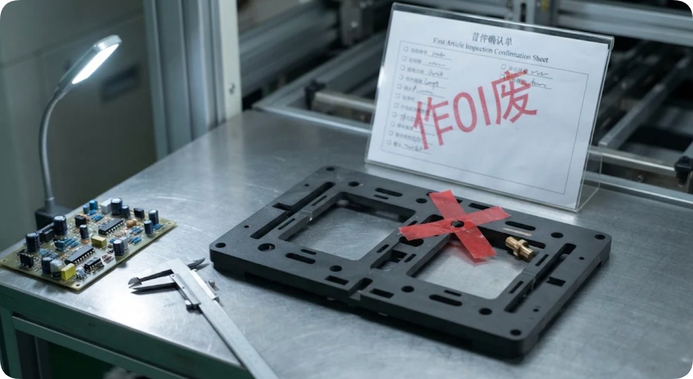
Because manual component insertion relies heavily on physical guides and optical verification, minor dimensional adjustments carry severe downstream ripple effects. A silkscreen change only affects text legend layers. Conversely, shifting a single through-hole coordinate invalidates three critical production tooling assets simultaneously:
- Wave Soldering Pallets: Custom CNC-milled titanium/synthetic pallets no longer align with component lead pin-out geometries.
- Plug-in AOI Inspection Profiles: Optical inspection algorithms generate false-fail alerts due to mismatched Golden Sample coordinate maps.
- First-Article Quality Records: Quality sign-offs tied to obsolete coordinate locations must be scrapped and re-executed.
Maintaining Quality Standards in Final Box-Build Assembly
For system integration, our Box Build Product Assembly & Packaging Service handles full turnkey manufacturing for industrial controllers, commercial IoT gateways, consumer devices, and sub-assemblies under ISO9001:2015 quality control systems. Assembly operations enforce dual-operator inspection checkpoints and strict physical material segregation across assembly cells to prevent part mixing.
Quality verification procedures are mandatory manufacturing controls. Bypassing dual-person verification during peak schedules degrades quality assurance standards. Similarly, physical work-cell boundaries protect against cross-model component contamination. If engineering revisions occur late in the product cycle, label art and outer packaging artwork changes are the safest to absorb, as they invalidate only packaging print stock rather than complex electro-mechanical sub-assemblies.

Burn-In Rack Allocation and Fixed Reliability Soaking
Thermal aging and burn-in testing represent fixed physical constraints. Our PCBA Aging Test & Reliability Testing Service utilizes environmental test chambers and load-testing racks where soak durations are governed strictly by engineering product profiles. Rack capacity cannot be artificially accelerated to compensate for upstream line delays.
Effective production management requires staggering chamber loading cycles based on validated file versions. Batches awaiting first-article sign-off following a late revision must not occupy active burn-in channels. Transparent communication regarding late design changes ensures customer delivery targets align with verified reliability soak times.
Engineering Change Impact Matrix
The following matrix categorizes common engineering change requests (ECOs) by their physical rework footprint, required asset rebuilds, and sign-off requirements:
| Change Stage / Location | Pre-Existing Assets | Invalidated Artifacts / Work | Re-Authorization Required |
|---|---|---|---|
| Stack-up / Hole Edit (Pre-CAM Release) | CAD drawings & layer notes | CAD drawings only (CAM drill & lamination files uncut) | Design Engineer |
| Stack-up / Hole Edit (Post-CAM Release) | NC drill programs, panelization, lamination specs | Drill tooling, panel layouts, bare-board WIP scrap | Design Engineer & CAM Manager |
| BOM Revision (Post-Kit Sealing) | Staged reels, bin labels, IQC sign-off logs | Kitting tags, pick sheets, feeder setup validation | Procurement & Line Supervisor |
| DIP Hole Coordinate Shift (Post-First Article) | Wave solder pallet, AOI algorithm, First-Article sheet | Pallet tooling, inspection profile, QA report sign-off | Process Engineer & QA Lead |
| Packaging Revision (Post-Assembly) | Printed box labels, master carton markings | Packaging stock & serial verification logs | Packaging Lead |
Published Service Specifications Reference
To maintain complete pricing and schedule integrity, the table below maps published engineering boundaries against custom project parameters requiring direct engineering review:
| Manufacturing Division | Published Capabilities | Custom Quote Parameters |
|---|---|---|
| PCB Fabrication & Prototyping | 1-36 layers; HDI; blind/buried vias; 0.4-8.0mm board thickness; 0.065mm min line/space; +/-0.025mm drill accuracy | Peak-season lead time priority rules; custom dielectric stack-up quotes |
| DIP Through-Hole Assembly | 4 insertion lines; selective AOI; 4 wave soldering units; 4 inline washing systems; IPQC/QA LOT standards | Custom wave fixture tooling lead times; high-density component lead bending cycles |
| Box-Build Product Assembly | ISO9001:2015 certification; dual-operator inspection; strict work-cell zoning; industrial & IoT enclosure support | Enclosure-specific cycle times (Takt time); specialized functional test fixture setup |
For quantitative analysis regarding ROI across EMS services, reference our financial analysis on multi-service manufacturing yields. Managing design freezes early safeguards production schedules, ensures reliable assembly quality, and eliminates peak-season scrap costs.
Frequently Asked Questions
1. How are post-seal BOM revisions processed?
A sealed component kit represents verified, physically staged inventory. When a BOM change occurs post-seal, an Engineering Change Order (ECO) halts feeder loading, empties affected staging locations, and re-verifies alternate part approvals before re-issuing material pick lists to the assembly floor.
2. Why do through-hole coordinate changes invalidate wave solder tooling?
Through-hole coordinates directly dictate physical CNC-milled wave solder pallets, automated optical inspection (AOI) vision algorithms, and First-Article Quality baselines. Altering a coordinate requires simultaneous updates across all three tooling assets to prevent inspection errors.
3. Which quality assurance procedures remain mandatory during peak production?
Dual-operator assembly verification checks and design-specified thermal burn-in soak durations remain non-negotiable. Maintaining strict inspection protocols protects against field failures and guarantees ISO9001 compliance under high production volumes.
4. What technical data is required to finalize an EMS quotation?
Final manufacturing quotations require fully validated Gerber files, NC drill data, detailed layer stack-up specifications, and complete BOM listings with verified Manufacturer Part Numbers (MPNs) to establish accurate tooling schedules and unit costs.
Tags: DIP assembly / product assembly / late change / seasonal planning /
Next: No more...