
Shell Mold, Industrial PC PCBA and Aging Test: The Enclosure Route That Cannot Be Reversed
My view, stated up front: an industrial computing programme rarely fails at the schematic. It fails at the point where someone picks how the housing will be formed, and then learns months later that the pick cannot be walked back. The electrical design is the part every team rehearses. The box around it is the part they improvise in a meeting that nobody scheduled properly.
I would rather argue about the forming route on day one, when the arguments are free, than on the week the plates arrive, when they are not.
NEWEI builds industrial pc solutions end to end, from a bare board to a sealed unit that survives a temperature chamber. What follows compares the three routes we see used for control board housings, and explains where each one quietly stops being the right answer.
Why the Housing Gets Decided Before the Schematic Is Signed
A housing is not a cosmetic shell drawn once the electronics are finished. It fixes the mounting pattern, the connector cut-outs, the height left for a heat spreader, and the path air takes when nothing in the unit is moving. On a fanless design, that last point alone decides the thermal budget.
Once a tool is cut, the geometry lives in steel. Adding half a millimetre of wall thickness, shifting a cut-out by two millimetres, or correcting a draft angle is not an edit. It is a second tool, a second lead time and a second invoice. Teams that treat the housing as a late styling decision pay for their mistake twice, and the second payment is the expensive one.
How Injection Forming Rewrites the Schedule
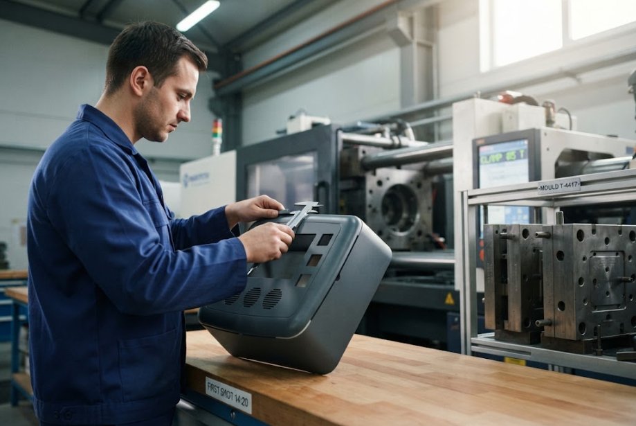
Injection forming is the route NEWEI is built around. Our mould partners run more than twenty machines, and the shop covers moulding, oil spraying, screen printing, pad printing and laser engraving under one roof. That matters, because a housing is rarely only a shape. It is a shape with a finish, a legend and a set of markings already applied to it.
Three variants are in daily use. Thermoplastic work heats pellets and forces them into a cavity, which is the familiar case. Reaction injection uses a thermosetting resin with low viscosity, and the lower viscosity allows larger parts than thermoplastic work usually permits. Metal injection begins with fine metal powder held in a carrier, and is chosen where the part has to behave like metal rather than like plastic. Choosing between them is a materials question, not a taste question, so it belongs in the review rather than after it.
The practical appeal of this family is the ramp. A 3D sample for fitting, a short trial run to check the screw bosses and connector clearances, then volume — with no minimum order quantity standing between the two. For a programme that is still finding its final shape, that ramp is worth more than any unit price. Injection work also carries the finish in the same tool, so the enclosure arrives already wearing its shell mold markings instead of needing a second supplier to add them.
Sheet Metal and Die-Cast, in Plain Terms
Sheet metal is the cheapest way to discover whether a concept works. Pressing and bending need modest tooling, a revision can often be handled by reworking the punch or the bend programme, and small volumes stay economic. The trade-offs are equally familiar: sharp edges, few compound curves, sealing that has to be designed rather than assumed, and a shielding plan that must be added deliberately.
Die-cast aluminium sits at the opposite end. It delivers rigidity, spreads heat well and produces a housing that feels like an instrument rather than a container. The tool is costly and slow to arrive, which is only sensible when the volumes justify it and the thermal load is high enough to need metal in the first place.
Where the Two Alternatives Stop Making Sense
The useful comparison is not which route is better in the abstract. It is which route survives the changes you have not thought of yet.
| Route | Tooling lead time | Change after freeze | Best fit |
|---|---|---|---|
| Injection moulded shell | Moderate, with 3D sample first | New tool for geometry, finish edits cheaper | Complex shape, integrated finish, ramping volume |
| Sheet metal | Short | Rework punch or bend programme | Low volume, flat panels, early concept builds |
| Die-cast aluminium | Long | New tool, no shortcuts | High thermal load, rigidity, established volume |
Read the rows as questions rather than a ranking. If the programme is still moving, the middle row is the one that will not punish you for moving with it. If it is not moving, the first two rows cost you capability you may eventually want back.
Fit Tolerances That Only Appear After Closure
Every interface between board and housing is a stack: outline tolerance, hole position, standoff height, screw torque, connector depth. Individually each number is small. Together they decide whether a cut-out sits flush or fights the cable, and whether a board flexes as the last screw goes in.
A small board makes this harder rather than easier. The FT-6200U-V1.0 industrial thin client board measures 146 mm by 105 mm and still carries six serial ports, dual Intel I211 gigabit Ethernet controllers, a SATA port, an mSATA slot and a DDR3L SO-DIMM socket. A board that dense leaves almost no unused area, so every mounting point has to be placed against a real constraint.
That density is also why the electrical side of a programme cannot be signed off in isolation. The FT-6200U-V1.0 industrial thin client board is one of the boards we assemble under our industrial computing PCBA programme, and the serial headers sit close enough to the board edge that the housing wall becomes part of the interface decision.

What a Long Dwell at Temperature Actually Proves
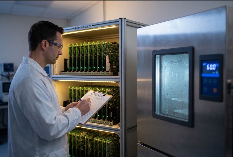
An aging test is not a formality bolted onto the end of a build. It places a finished assembly under the conditions it will actually meet, keeps it working for between seventy-two hours and seven days, and records what happens. What it produces is not reassurance. It is evidence, and evidence is what a customer can take to their own customer.
| Assembly | Condition | Duration |
|---|---|---|
| Blood glucose meter board | Room temperature, up to 500 simulated cycles | About 48 hours |
| Transport camera board | 60 degrees Celsius, 70 percent humidity | 72 hours |
| Solar storage controller | Continuous charge and discharge, 3 cycles | 24 hours |
| Environmental controller | Continuous control and network traffic | 24 hours |
Two details separate a real programme from a promised one. The first is that failures found during the dwell are traced back into the process rather than simply scrapped. The second is that some tests cannot be run indoors at all, which is why drop, vibration and salt spray work is handled with a partner laboratory instead of being claimed in-house. If a supplier will not say which tests leave the building, they have not thought about the question.
Applications Where the Choice Is Already Made
Some deployments remove the decision entirely. A production line panel that must survive wash-down ends up in a moulded shell with a gasket, because sealing a folded panel is more trouble than it is worth. An AGV controller sees vibration and thermal cycling that push it toward die-cast, where the aluminium does double duty as a heat sink.
A machine vision station usually lands on sheet metal, because the enclosure changes every time the fixture changes. An outdoor cabinet gateway wants a moulded cover with the antenna and connector legends already printed into it. A bedside medical unit wants a surface that can be wiped and a housing that will not flex when a nurse grips it. Across all of these, the constant is that our electronics manufacturing services hold form, board and verification in one chain, so the route argument happens once instead of three times.
Questions to Bring to the First Mould Review
Bring the awkward questions early. What is the realistic volume band for the next two years, and what happens if it doubles? Which interfaces are already fixed by a connector supplier, and which can still move? How will the board be held during assembly, and does the housing provide that datum or fight it?
Then ask about the finish, the marking method and the shielded sections, because those are the parts that turn a cheap tool into an expensive programme. Finally, ask what evidence comes back after the dwell. A supplier who can answer that without checking should be treated as a partner. One who cannot is still a quote. To see how the rest of the chain fits together, learn more about our manufacturing capabilities, then send the drawing and let us tell you which route we would take.
Tags: shell mold / enclosure manufacturing /
Prev: Shell Mold, Product Assembly and Smart Home PCBA: Which Compliance File Travels With Which Half
Next: SMT Assembly and Industrial PC PCBA: The Evolution Written on a Witness Coupon