
DIP Assembly and PCBA Three-Proofing Paint: Why Through-Hole Is Not Retiring Yet
Every few years the same claim circulates: through-hole technology is finished, and any board still carrying it is a relic. The production data says otherwise. Walk the lines building industrial controllers, EV chargers, solar inverters, and grid protection relays and you will find through-hole components holding the exact positions where failure would be expensive. The reason is not nostalgia. A leaded part passing through a plated hole carries current, survives vibration, and tolerates thermal cycling in ways a soldered pad simply cannot match, and the growth markets of this decade are precisely the ones that demand all three. At the same time, the boards coming off those lines are being coated more often than ever, because the environments they ship into have got harsher. If you are planning capacity, start from through-hole insertion and soldering service and read the duty cycle of your target application before you read the component density.
The Obituary That Never Ran
The prediction was reasonable when it was made. Surface mount won on almost every metric that mattered to consumer electronics: it is smaller, it is cheaper at volume, it places faster, and it lets both sides of a board carry parts. What the prediction missed is that the growth in electronics has moved away from the applications where those metrics dominate. The products with the steepest volume curves now are the ones that sit in a cabinet on a factory wall, under the bonnet of a vehicle, or on a pole beside a road, and those applications care about surviving fifteen years of heat, cold, humidity, and vibration rather than about being thin. Through-hole holds its ground wherever the consequence of a joint cracking is a service call rather than a refund.
Where Surface Mount Cannot Follow
The physics is unglamorous and does not change. A surface mount joint is a fillet of solder holding a component against a flat pad, and it is loaded in shear whenever the board flexes or the part is pushed. A through-hole joint has a lead that passes through the board and is soldered on the far side, so the mechanical load is carried by the barrel of the hole rather than by the fillet alone. That difference decides the outcome for anything heavy, anything plugged and unplugged repeatedly, and anything carrying real current. Connectors, terminal blocks, large electrolytic capacitors, transformers, and relays stay leaded for exactly this reason, and no amount of placement accuracy changes the arithmetic. The SMT Assembly side handles the thousands of small passive and active parts brilliantly, and it is the right choice for them, but it is not a universal answer.
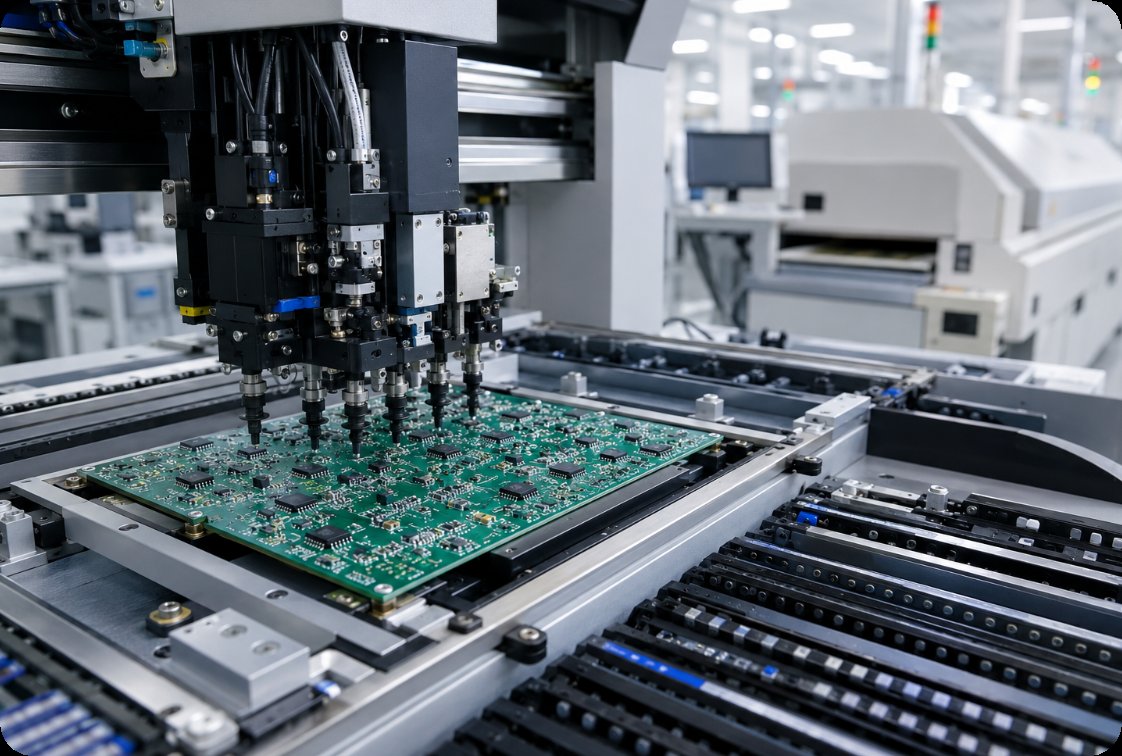
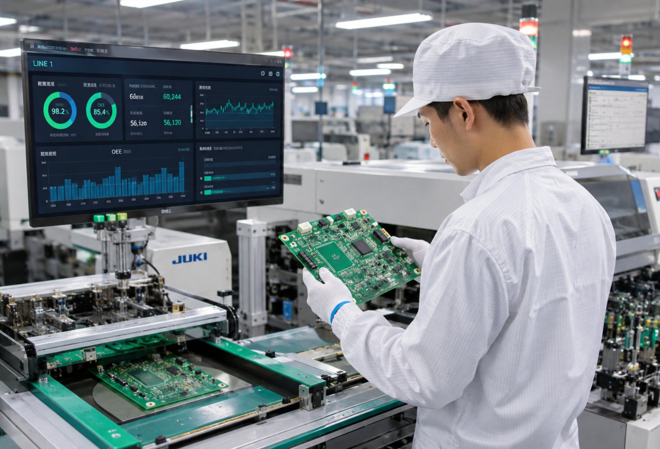
An SMT line placing the small passive and active parts, which is where surface mount remains unambiguously the right process.
A Comeback Driven by Harsher Duty
Three markets are pulling through-hole volume up rather than down. Electrified transport needs connectors and power devices that carry hundreds of amps and survive road vibration for a decade. Renewable energy needs inverter and protection boards that live outdoors through daily thermal swings. Industrial automation needs controllers that run twenty-four hours a day in cabinets that reach seventy degrees internally. None of these are nostalgic applications, and none of them can be built entirely from parts resting on pads. The interesting consequence is that board designers now routinely specify a mixed build on purpose rather than by compromise: small parts placed by machine, heavy parts inserted and soldered through the board, each process used where it wins.
Mixing Both Processes across One Panel
A mixed-technology board is built in a deliberate order, and getting the order wrong is the most common source of rework. The surface mount side goes through the reflow oven first, while the board is still flat and empty of tall parts. The through-hole components are inserted afterwards and soldered in a second pass, which protects the small parts from a second thermal cycle and gives the operator clear access to the insertion points. Where a few through-hole parts sit among many surface mount ones, selective soldering has largely replaced the old wave solder bath, because it solders one joint or one group at a time without flooding the underside of the board. The DIP Assembly stage is therefore not a fallback for parts that could not be placed; it is a planned step with its own fixtures, its own programme, and its own inspection criteria.
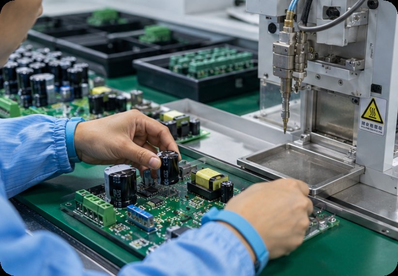
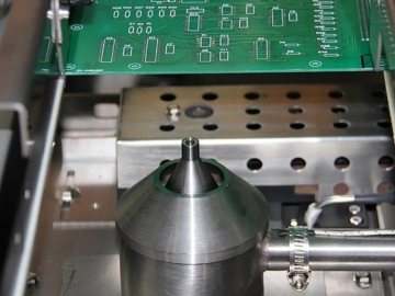
Through-hole components inserted after reflow and soldered selectively, a planned second pass rather than a compromise.
Selective Soldering Replaces the Wave
The shift from wave soldering to selective soldering is one of the quieter changes on the factory floor and one of the more consequential. A wave bath solders everything on the underside of a board at once, which is fast and unforgiving: it thermal-shocks the whole assembly and can lift or bridge parts that were never meant to see that heat again. A selective machine moves a small solder nozzle to each joint under programme control, with a preheat and a dwell tuned per location. It is slower per board and dramatically better per joint, and it makes mixed-technology builds economical at volumes where a wave line would have been impossible to justify. For the high-mix industrial work that now dominates this sector, selective soldering is the default rather than the exception.
The Coating That Decides Service Life
The most visible trend on these lines has nothing to do with soldering at all. Boards that used to ship bare now leave with a conformal coating, and the reason is that the environments have got harder. Condensation inside an outdoor enclosure, salt-laden air near a coast, sulphur in an industrial atmosphere, and the everyday combination of dust and humidity all attack a bare assembly slowly and then suddenly. The PCBA Three-Proofing Paint process deposits a thin protective film over the finished assembly, sealing the joints and the exposed copper against moisture, salt, and fungal growth. What has changed is not the chemistry but the default: coating used to be something a customer asked for on a harsh-environment product, and it is increasingly written into the build instructions before the first board is populated.
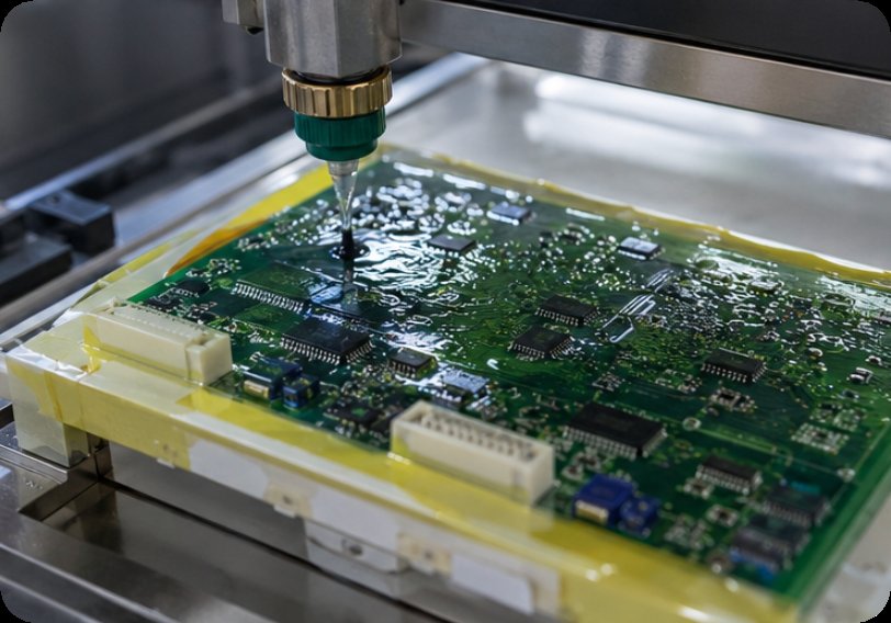
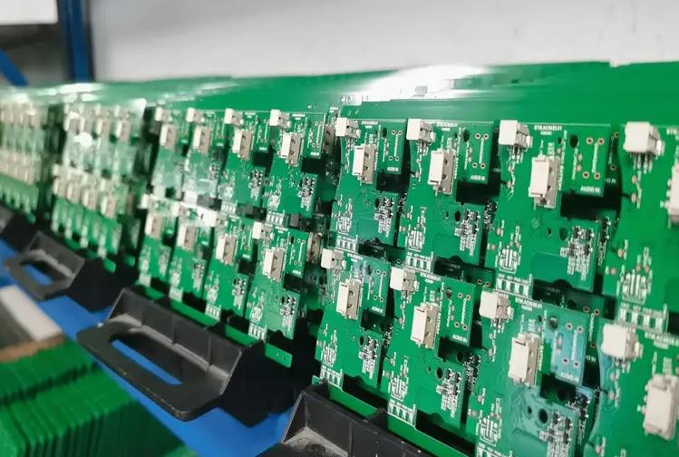
A conformal coating applied over the finished assembly, sealing through-hole joints and exposed copper against moisture and contamination.
Inspection Once the Joint Cools
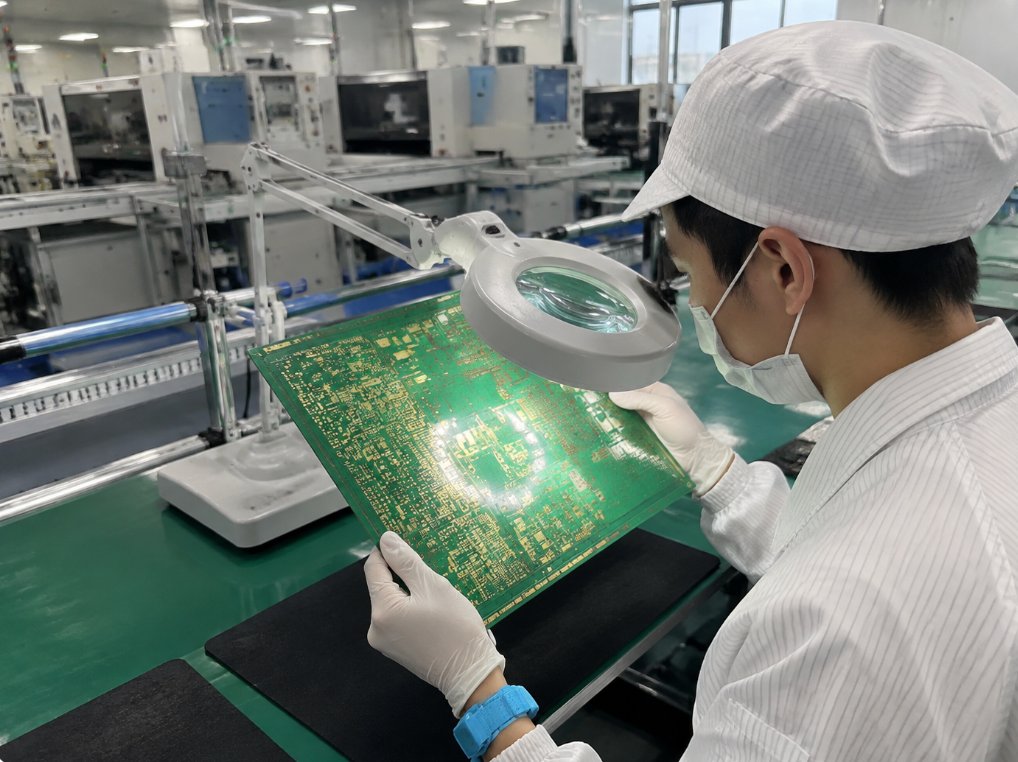
Through-hole joints are inspected differently from surface mount ones, because what matters is inside the hole rather than beside it. The acceptance criterion is barrel fill: how completely solder has wicked up the plated barrel around the lead. A joint can look perfect from above and be substantially hollow underneath, which is why optical inspection alone is not sufficient on this process. X-ray or a destructive cross-section on a sample from each lot is the usual answer, and the results belong in the build record rather than in an engineer's notebook. The table below maps each process step to what gets checked and what the usual failure looks like.
| Process step | What gets checked | Acceptance focus | Usual failure |
|---|---|---|---|
| SMT reflow | paste volume, placement, reflow profile | fillet shape, tombstoning | voiding under large pads |
| Through-hole insertion | lead protrusion, component seating | correct part, correct orientation | part not fully seated |
| Selective soldering | barrel fill, wetting, bridging | fill percentage per joint | incomplete fill from low preheat |
| Conformal coating | coverage, thickness, cure | continuous film, no bare spots | shadowing under tall parts |
| Final electrical test | continuity, isolation, function | pass per test programme | residual flux affecting isolation |
Specifying a Line for the Next Decade
The practical conclusion for anyone specifying a build today is that the question has stopped being surface mount or through-hole, and has become where each one belongs and what protects the result afterwards. Put the small parts on the placement machine, put the connectors and power devices through the board, solder the second pass selectively rather than by flood, and coat the finished assembly unless the product genuinely lives in a benign environment. That sequence is now the norm in industrial and transport electronics rather than the exception. Our electronics manufacturing services team runs the placement, insertion, selective solder, coating, and inspection steps under one roof, and a DIP assembly case study from an industrial controller line shows how the mixed sequence works on a real product. Send us your bill of materials and your operating environment and we will tell you which parts belong through the board and what the coating needs to survive.
Tags: DIP / conformal coating / SMT /
Next: PCB Fabrication and PCBA: Three Lines That Disappeared From the Board Quote