
Custom Electronic Devices PCBA and DIP Assembly: The Lines the File Left Unwritten
Ask five engineers what a customer file contains and the answers sound almost identical: Gerber data, a bill of materials, a stack-up, and now and then a test request. Ask the same five what the file leaves out and the answers get much longer. Nobody writes down the room the product will sit in, which connector is expected to carry load, or how long a finished board should run before somebody signs it off. None of that is carelessness. Those are the parts of a project a drawing was never built to hold.
What makes the gap worth studying is where it gets closed. In a custom programme the missing lines are filled in on the factory floor, in the days between the first panel and the shipping label, by people committing to decisions that will still matter years later. This article looks at three places where that burden lands hardest.
Where the Paperwork Normally Stops
A manufacturing file is a boundary document. It describes a board and the parts that sit on it, then stops, because everything past that point depends on facts the customer holds but has never thought to write down. The file is complete for the task it was drawn to do: telling a machine where to place components and telling a buyer what to order. Everything else is judgement. Whether a joint survives vibration depends on how a part is attached, not only where. Whether a coating is appropriate depends on condensation rather than on the catalogue category the product was filed under.
Connectors Nobody Listed as Load-Bearing
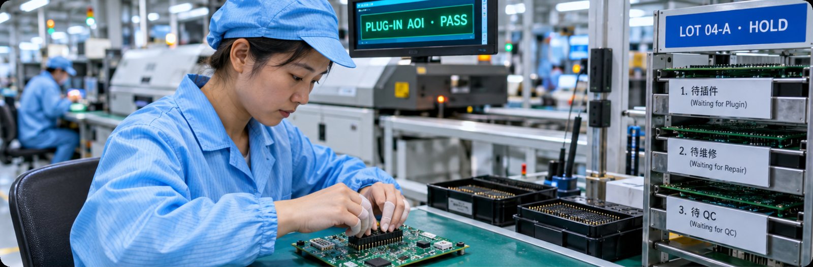
Through-hole work is where the physical side of a board is decided. A connector the customer reads as a signal path is often, in the field, a handle: it takes the force of a cable being pulled or a technician leaning on the housing. DIP assembly services are where that distinction becomes a joint able to carry load, because a properly filled through-hole barrel behaves very differently from a surface pad under repeated mechanical stress.
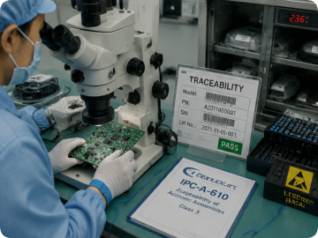
The same stage decides something less visible: whether lots stay apart. A through-hole line carries more hand work than a placement line, and with it more chances for a board to wait in the wrong place. The answer here is a set of separately identified holding areas for boards awaiting insertion, repair, quality inspection, QA review, and confirmed rejects, so mixed lots cannot quietly form. Plug-in AOI checks components for wrong part, omission and reversed orientation, and lot sampling under IPQC and QA holds the pass-through rate where it belongs.
A Duty Cycle That Was Never Stated
Nothing in a parts list says how often the product will be switched on, and that single missing number changes more of the build than most customers expect. A controller running continuously for years and a handheld that wakes for two minutes at a time can share a schematic and still need different component grades and different thermal assumptions. The file describes the circuit. It cannot describe the rhythm.
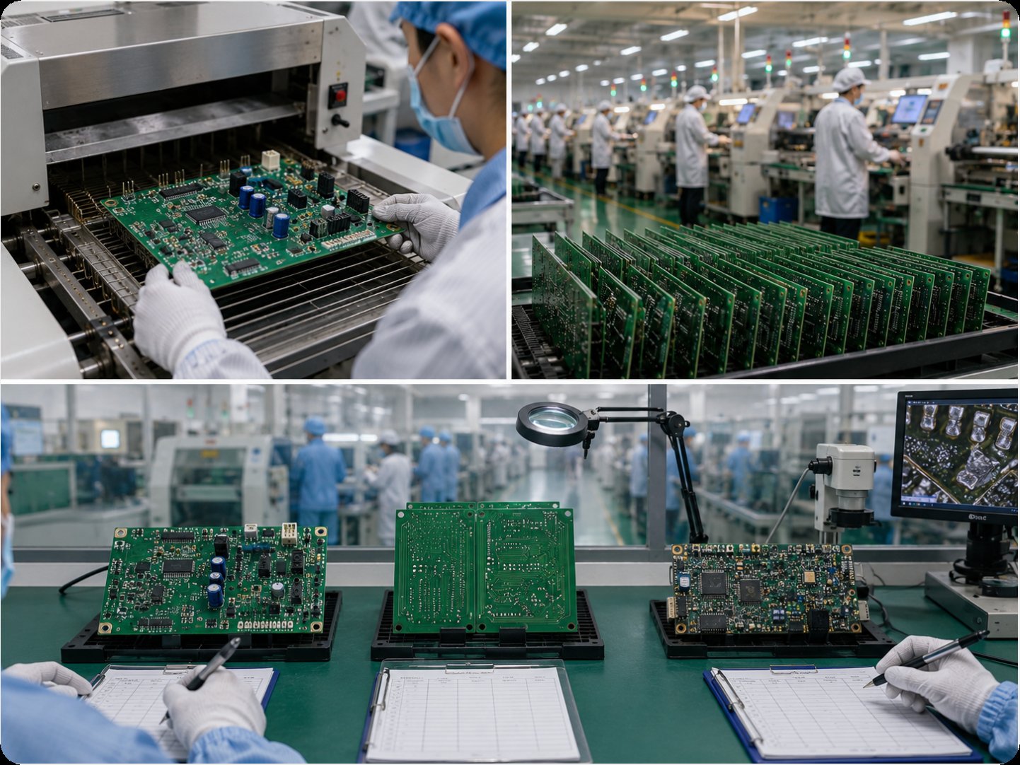
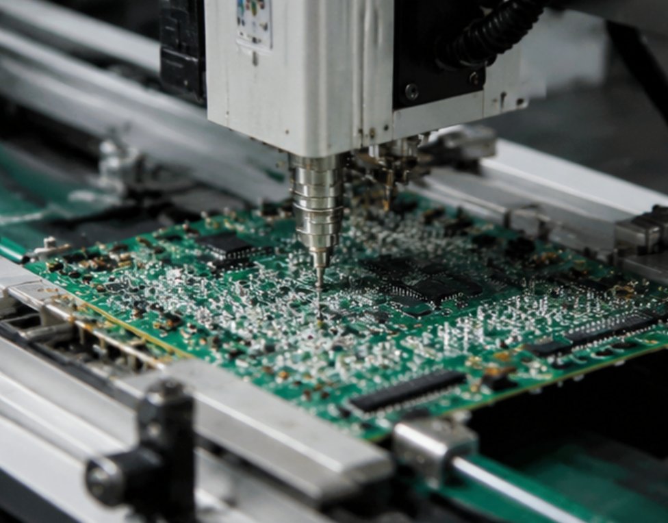
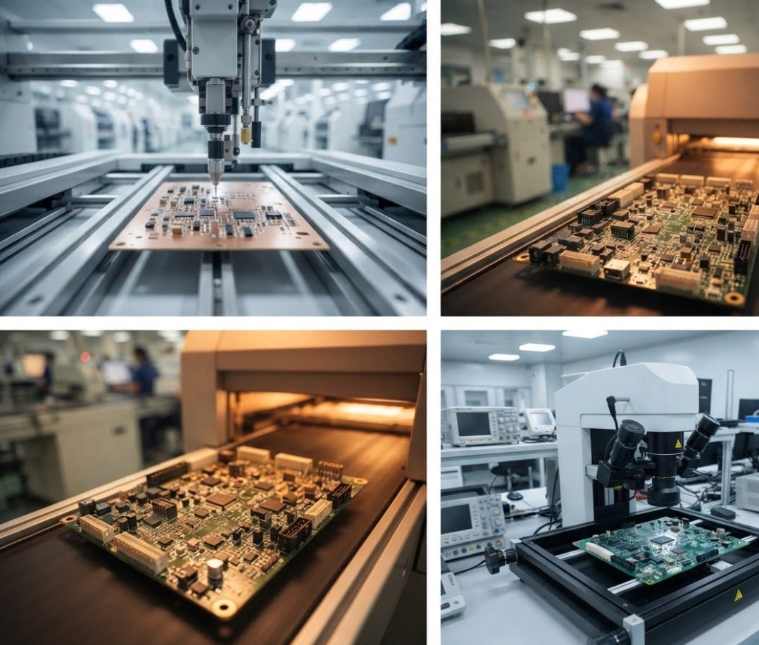
This is where upstream choices matter more than downstream inspection. Component derating, the margin left on a capacitor or a regulator, is set when the line is programmed and is hard to correct later without a new revision. The SMT assembly stage is where those choices turn physical, across fully automatic high-speed lines with solder paste inspection, multi-zone reflow and X-ray verification behind them. Getting the margin right at that moment costs less than discovering the rhythm was wrong after a season in the field.
Two Boards With One Silent Difference
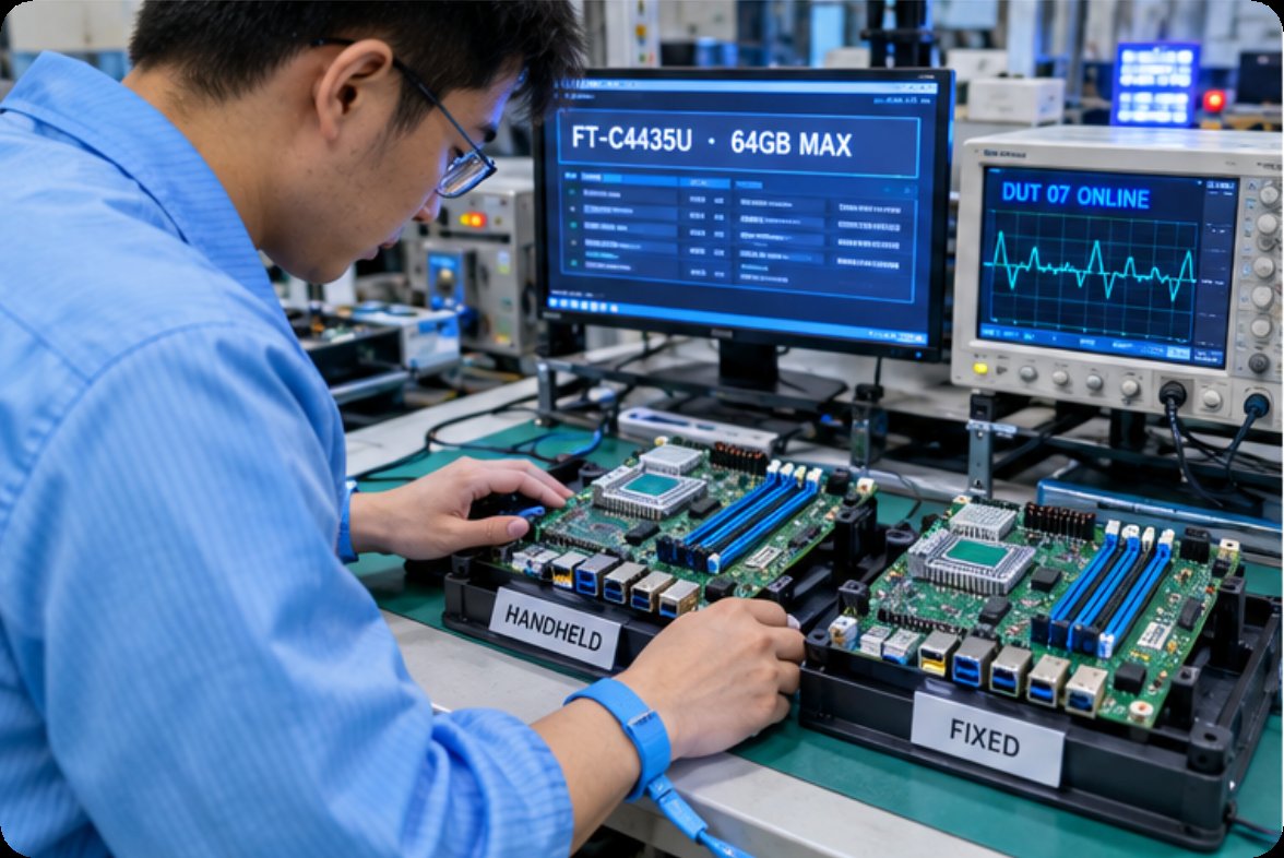
Custom device work sharpens the missing line, because two products can look identical on paper and behave nothing alike. A board built for a handheld and one built for a fixed installation may share a form factor, a processor family and a pin-out, and still need different answers about shock, humidity and service access. Nothing in the shared artwork records which of the two the customer is actually buying.
The practical response is to treat the platform as a starting point rather than a specification. A board in the Smart Medical Motherboard FT-C4435U class, for instance, carries an eighth-generation Whiskey Lake Core i3, i5 or i7 processor, two DDR4 SO-DIMM slots up to 64GB, triple independent display output through DDI, LVDS or EDP and VGA, four general-purpose inputs and outputs, two UART ports and a Gigabit controller, with ACPI 4.0 support for smart batteries and a smart EC chip. Those figures describe what the board can do. What the deployment does with them is the part the customer has to say out loud.
How Long Should the Chamber Run
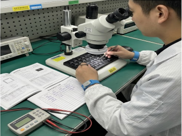
Burn-in exists purely to answer an unwritten question: how long a design has to prove itself before anyone believes it. The service window is a continuous simulated run of 72 hours to seven days, with occasional on-off impact testing, recording performance data throughout so the process can be corrected rather than merely passed. That range is wide on purpose. A short soak screens a process. A long one starts to say something about the product.
What the customer rarely supplies is which end of the range applies. The answer is usually reverse-engineered from the service scenario, and the examples on file show how far apart those answers sit. A medical blood glucose meter board can be exercised through as many as 500 simulated tests at room temperature over roughly 48 hours. A transport camera board can be soaked at 60 degrees Celsius and 70 percent humidity for 72 hours. A solar storage controller may run through three charge and discharge cycles across 24 hours, while an environmental controller for a livestock building runs continuously with network communication for a day. Four ordinary products, four definitions of proof.
The methods follow the same logic, from room-temperature operation through high and low temperature soaks to alternating temperature and humidity cycling, with drop, vibration and salt spray testing treated as neighbouring evidence. Where a condition cannot be reproduced inside the plant it goes to a partner laboratory rather than being approximated. PCBA aging test work matters most for custom products, because a standard part arrives with field history behind it and a custom one brings nothing but its own first batch.

A Table of Decisions and Their Owners
Placing the three stages side by side makes the division of labour visible, and shows how much of the work is interpretation rather than fabrication. Read it as a handover checklist.
| Stage | What the file supplies | What it omits | Who settles it on the floor | What an unsettled call costs |
|---|---|---|---|---|
| DIP Assembly | Placements and a parts list | Which connectors carry mechanical load | Plug-in AOI, IPQC and QA lot sampling | Rework, and boards routed to the wrong holding area |
| Custom Electronic Devices PCBA | Gerber data and a stack-up | The environment the unit will really live in | Platform experience and early derating choices | A first batch that looks correct and ages badly |
| Aging Test | A test request, when one is issued | Duration, temperature and humidity curve | Conditions reverse-engineered from the service scenario | A warranty period nobody is able to defend |
Two facts jump out of that table. The omissions follow a pattern: every one of them is about use rather than construction, which is why they stay invisible on a drawing. And the cost of an unsettled call is rarely paid by the party who left it open. It lands downstream, as rework, as an early failure, or as a warranty claim argued from data that was never collected.
A Thinner Sketch Is Not a Smaller Job
There is a reasonable instinct that a short file means a simple product. In a custom programme the opposite is usually true. A thin file means the customer is buying interpretation, and interpretation is the expensive part of the job because it consumes engineer attention rather than machine time. Handled well, that is a service rather than a burden. Our electronics manufacturing services cover the path from bare board through placement, through-hole work, testing and final assembly under ISO 9001:2015, ISO 13485 and IATF 16949, so answers to the open questions can be written down and repeated on the next order rather than rediscovered.
What Changes Once Both Sides Read the Same Sheet
The improvement is not a longer document. It is an agreed list of which lines the customer owns and which the factory owns, reviewed once, early, before the first panel is committed. When that list exists, the three stages above stop being places where decisions hide and become places where they are recorded. If you would like to see how the work is staged, you can learn more about our manufacturing capabilities, then send us the file you have today and the questions you have not answered yet.
Tags: DIP assembly /custom electronic devices PCBA / PCBA test bench /
Prev: SMT Assembly and EMS Electronic Manufacturing: Reliability as a Set of Permissions
Next: No more...